82 Chapter 7—Bus Outs
DM1000 Version 2—Owner’s Manual
Bus Out 1–8
The Bus Out 1–8 section mixes signals routed from Input Channels to the specified buses,
processes them using on-board EQ, compressor, etc., then routes them to the specified out-
put connectors or I/O cards.
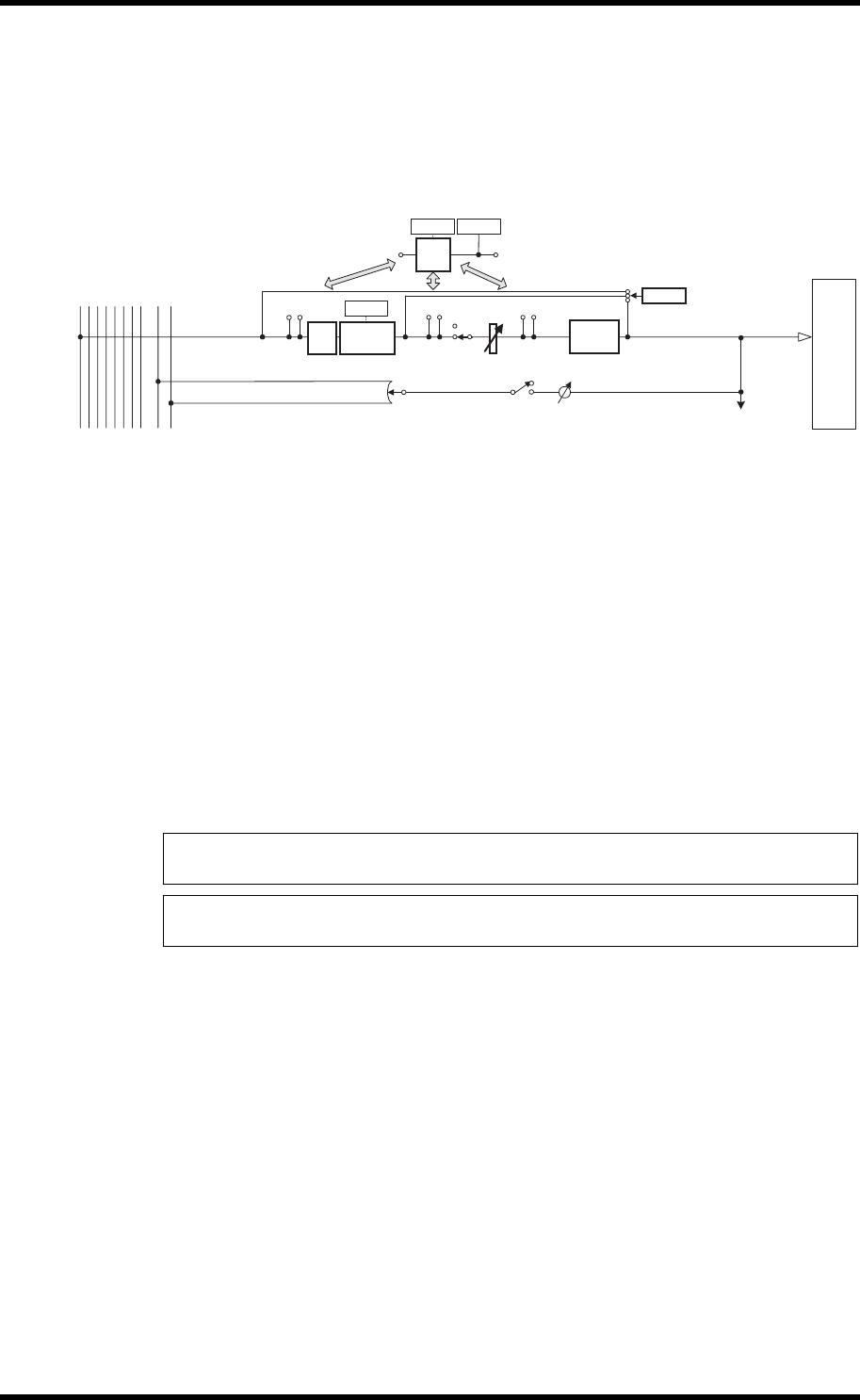
The following diagram illustrates the Bus Out signal flow.
• INSERT
•ATT (Attenuator)
•4 BAND EQ (4-band equalizer)
• COMP (Compressor)
• ON (On/Off)
• LEVEL
• OUTPUT DELAY (Output delay)
• METER
The parameters and sections listed above are identical to those for the Stereo Out. For more
information, refer to the explanation the Stereo Out (see page 81).
• Bus to Stereo
Bus Out 1–8 signals are also routed to the Stereo Bus. In addition to the ON, LEVEL, and
other parameters, you can also set the Send Level, On/Off, Pan, and other parameters.
Tip: You can also pair adjacent odd-even buses (in this order) for stereo operation (see
page 89).
Note: By default, channels 1–8 and 9–16 of Slots 1 and 2 are patched to the Bus Out 1–8
outputs. However, you can change this patching on the Output Patch page.
OUTPUT PATCH
OUTPUT
DELAY
METER
ATT
4BAND
EQ
INSERT
INSERT
LEVEL
ON
COMP
METER
(Gain Reduction)
INSERT
METER
METER
(Out Meter)
STEREO L
STEREO R
BUS1
BUS2
BUS3
BUS4
BUS5
BUS6
BUS7
BUS8
TO INPUT PATCH
PA N
BUS to STEREO
LEVEL
ON
BUS 1(...8)
BUS 1(...8)


