


Effects Parameters 313
DM1000 Version 2—Owner’s Manual
Appendix
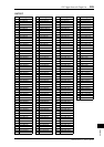
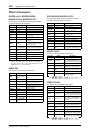
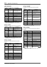
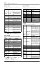
HQ. PITCH
One input, two output high-quality pitch shifter.
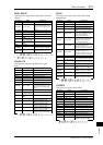
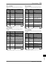
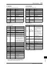
DUAL PITCH
Two input, two output pitch shifter.
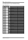
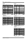
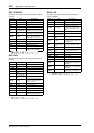
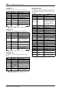
ROTARY
One input, two output rotary speaker simulator.
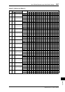
RING MOD.
Two input, two output ring modulator.
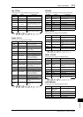
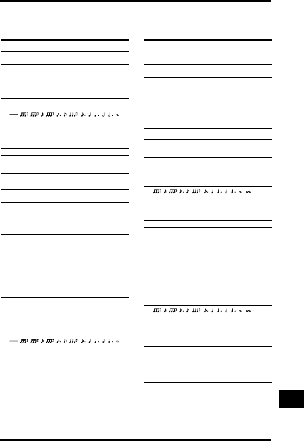
MOD. FILTER
Two input, two output modulation filter.
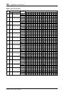
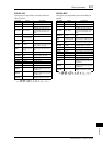
DISTORTION
One input, two output distortion effect.
Parameter Range Description
PITCH
–12 to +12 semi-
tones
Pitch shift
FINE –50 to +50 cents Pitch shift fine
DELAY 0.0–1000.0 ms Delay time
FB. GAIN –99 to +99%
Feedback gain (plus values for
normal-phase feedback, minus
values for reverse-phase feed-
back)
MODE 1–10 Pitch shift precision
SYNC OFF, ON Tempo parameter sync on/off
NOTE
1
1.
(Maximum value depends on the tempo setting)
Used in conjunction with
TEMPO to determine DELAY
Parameter Range Description
PITCH 1
–24 to +24 semi-
tones
Channel #1 pitch shift
FINE 1 –50 to +50 cents Channel #1 pitch shift fine
LEVEL 1 –100 to +100%
Channel #1 level (plus values for
normal phase, minus values for
reverse phase)
PAN 1 L63 to R63 Channel #1 pan
DELAY 1 0.0–1000.0 ms Channel #1 delay time
FB. G 1 –99 to +99%
Channel #1 feedback gain (plus
values for normal-phase feed-
back, minus values for
reverse-phase feedback)
PITCH 2
–24 to +24 semi-
tones
Channel #2 pitch shift
FINE 2 –50 to +50 cents Channel #2 pitch shift fine
LEVEL 2 –100 to +100%
Channel #2 level (plus values for
normal phase, minus values for
reverse phase)
PAN 2 L63 to R63 Channel #2 pan
DELAY 2 0.0–1000.0 ms Channel #2 delay time
FB. G 2 –99 to +99%
Channel #2 feedback gain (plus
values for normal-phase feed-
back, minus values for
reverse-phase feedback)
MODE 1–10 Pitch shift precision
SYNC OFF, ON Tempo parameter sync on/off
NOTE 1
1
1.
(Maximum value depends on the tempo setting)
Used in conjunction with
TEMPO to determine Channel
#1 delay
NOTE 2
1
Used in conjunction with
TEMPO to determine Channel
#2 delay
Parameter Range Description
ROTATE STOP, START Rotation stop, start
SPEED SLOW, FAST
Rotation speed (see SLOW and
FAST parameters)
SLOW 0.05–10.00 Hz SLOW rotation speed
FAST 0.05–10.00 Hz FAST rotation speed
DRIVE 0–100 Overdrive level
ACCEL 0–10 Acceleration at speed changes
LOW 0–100 Low-frequency filter
HIGH 0–100 High-frequency filter
Parameter Range Description
SOURCE OSC, SELF
Modulation source: oscillator or
input signal
OSC FREQ 0.0–5000.0 Hz Oscillator frequency
FM FREQ. 0.05–40.00 Hz
Oscillator frequency modulation
speed
FM DEPTH 0–100%
Oscillator frequency modulation
depth
SYNC OFF, ON Tempo parameter sync on/off
NOTE FM
1
1.
Used in conjunction with
TEMPO to determine FM FREQ
Parameter Range Description
FREQ. 0.05–40.00 Hz Modulation speed
DEPTH 0–100% Modulation depth
PHASE
0.00–354.38
degrees
Left-channel modulation and
right-channel modulation phase
difference
TYPE LPF, HPF, BPF
Filter type: low pass, high pass,
band pass
OFFSET 0–100 Filter frequency offset
RESO. 0–20 Filter resonance
LEVEL 0–100 Output level
SYNC OFF, ON Tempo parameter sync on/off
NOTE
1
1.
Used in conjunction with
TEMPO to determine FREQ
Parameter Range Description
DST TYPE
DST1, DST2,
OVD1, OVD2,
CRUNCH
Distortion type (DST = distor-
tion, OVD = overdrive)
DRIVE 0–100 Distortion drive
MASTER 0–100 Master volume
TONE –10 to +10 Tone
N. GATE 0–20 Noise reduction