


136 Chapter 11—Surround Functions
DM1000 Version 2—Owner’s Manual
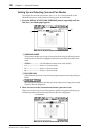
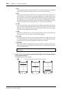
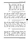
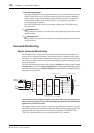
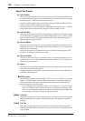
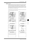
A Surround pan graphs
These graphs display the trajectory patterns and the current pan positions for the Input
Channels. Move the cursor to the desired channel’s graph, then rotate the Parameter
wheel to adjust the pan settings along the selected trajectory pattern. Turning on the
[GRAB] button enables you to use the Joystick to set the surround pan of the cur-
rently-selected Input Channel.
Press [ENTER] while the cursor is on the graph to display the Ch Edit page for the
selected channel.
B parameter box
This parameter box enables you to move the surround pan setting of the selected chan-
nel left and right.
C parameter box
This parameter box enables you to move the surround pan setting of the selected chan-
nel front and rear.
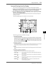
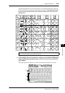
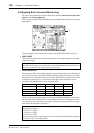
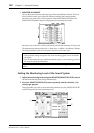
Surround Monitoring
About Surround Monitoring
The DM1000 features comprehensive surround monitoring functions that enable you to
monitor, in the optimum environment, the surround sources in the Buses or those input
from Slot 1 or 2. These functions include down mixing (which enables you to monitor sig-
nals on fewer channels) and fine-tuning of surround channel signals according to the mon-
itoring environment.
The surround monitoring functions also feature an oscillator for testing speakers, a mon-
itoring matrix for down mixing, Bass Management for optimizing channel signals for the
monitoring environment, and monitor alignment using individual Attenuator and Delay
parameters for each speaker.
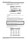
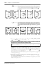
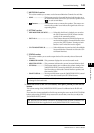
To monitor the Surround Monitor signal via the surround system, you must connect
the system to the output connectors on the DM1000, then patch the Surround Monitor
signal source to these connectors.
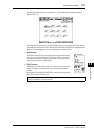
For example, if the surround system is connected to the OMNI OUT connector, press the
[OUTPUT PATCH] button repeatedly until the Out Patch | OMNI Out page appears. This
page will enable you to patch the surround channel (indicated as “SURR XXX” where
“XXX” is the channel name) to the corresponding OMNI OUT connector.
MONITOR
LEVEL
MONITOR MATRIX OUT
FROM CONTROL ROOM L/R TO CONTROL ROOM DIMM
C-R to SURROUND MONITOR
8
BUS1-8
8
STEREO
2
BUS
DIMM
MONITOR
MATRIX
MONITOR
ALLIGNMENT
BASS
MANAGEMENT
SLOT2 1-8
8
8
SLOT
8x8
Patch
SLOT1 1-8
8
8
PINK NOISE
500-2kHz
BPF
1kHz, 50Hz
SURROUND
MONITOR
TO OUTPUT PATCH