


Control Surface 21
DM1000 Version 2—Owner’s Manual
2
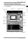
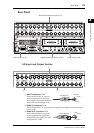
Control Surface & Rear Panel
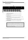
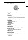
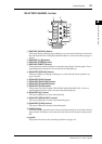
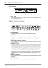
SELECTED CHANNEL Section
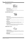
A ROUTING [DISPLAY] button
This button displays a Routing page, enabling you to route selected channels to the desired
Bus, and adjust the level of the signals routed from Buses 1–8 to the Stereo Bus (see page 71
and 85).
B ROUTING [1]–[8] buttons
C ROUTING [STEREO] button
D ROUTING [DIRECT] button
These buttons select the desired Bus for routing the selected Input Channel signals. The cor-
responding button indicator for the currently-selected Bus lights up.
E EQUALIZER [DISPLAY] button
This button displays an EQ page, enabling you to set the selected channel equalizer (see
page 67 and 68).
F EQUALIZER [HIGH] button
G EQUALIZER [HIGH-MID] button
H EQUALIZER [LOW-MID] button
I EQUALIZER [LOW] button
These buttons select the EQ band (HIGH, HIGH-MID, LOW-MID, LOW). The corre-
sponding button indicator of the currently-selected band lights up.
J EQUALIZER [Q] control
This control adjusts the currently-selected band Q.
K EQUALIZER [FREQUENCY] control
This control adjusts the currently-selected band frequency.
L EQUALIZER [GAIN] control
This control adjusts the currently-selected band gain.
M [GRAB] button
This button enables Joystick control of the surround pan setting for the currently-selected
Input Channel. This button can be turned on only when the surround pan setting is avail-
able.
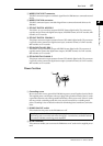
N Joystick
The Joystick is used to set the surround pan position (see page 131).
EQUALIZER
LOW
HIGH
GAIN
Q
FREQUENCY
LOW MID
HIGH MID
ROUTING
12
34
56
78
STEREO DIRECT
DISPLAY
DISPLAY
SELECTED CHANNEL
GRAB
2
1 5
6
J
7
8
9
K
MN
3
L
4