


278 Chapter 20—Other Functions
DM1000 Version 2—Owner’s Manual
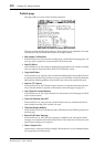
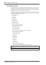
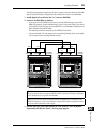
At this time, the trigger signal is output from the CONTROL port when you operate the
assigned parameters or controls.
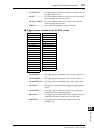
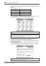
■ Parameters available in the INPUT section
• TALKBACK/DIMMER .......................Same as the MONITOR [TALKBACK] and
[DIMMER] button functions.
• BUS/SLOT ............................................Same as the MONITOR [BUS] and [SLOT] but-
ton functions.
• STEREO/2TRD1/2TRD2....................Same as the MONITOR [STEREO], [2TRD1],
and [2TRD2] button functions.
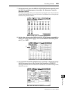
Tip: Refer to the next page for a complete list of assignable parameters and controls.
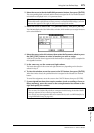
No Assign AUX1 ON
TALKBACK :
DIMMER AUX8 ON
BUS ST ON
SLOT CH1 ON UNLATCH
STEREO :
2TRD1 CH48 ON UNLATCH
2TRD2 BUS1 ON UNLATCH
TALKBACK UNLATCH :
DIMMER UNLATCH BUS8 ON UNLATCH
BUS UNLATCH AUX1 ON UNLATCH
SLOT UNLATCH :
STEREO UNLATCH AUX8 ON UNLATCH
2TRD1 UNLATCH ST ON UNLATCH
2TRD2 UNLATCH UDEF1
CH1 ON :
: UDEF12
CH48 ON
BUS1 ON
:
BUS8 ON
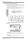
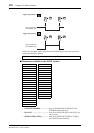
Trigger signal polarity =
Output signals from
the CONTROL port
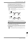
Trigger signal polarity =
Output signals from
the CONTROL port