


374 Appendix D: Options
DM1000 Version 2—Owner’s Manual
Appendix D: About Optional Product
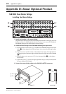
MB1000 Peak Meter Bridge
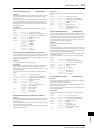
Installing the Meter Bridge
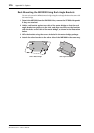
1 Attach the brackets to the meter bridge.
Align the holes on the lower part of the meter bridge with the holes on the upper part of the
brackets (as shown in the illustration below), then use four 8 mm screws (
1) included in
the MB1000 package to affix the brackets to the meter bridge.
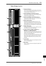
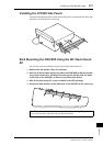
2 Install the meter bridge to the DM1000 following the steps below:
a) Insert two of four 12 mm screws (
2-2) included in the MB1000 package into the lower
holes (
2-2), then tighten them with your fingers. Leave the screws projecting by about
4 mm.
b) Align these screws with the notches on the included meter angles, then align the holes
on the upper part of the meter angles with the holes on the upper part of the DM1000
(
2-1).
c) Insert the other two 12 mm screws (
2-1) into the upper holes (2-1), then tighten
them securely.
d) Tighten the screws (
2-2) that were finger-tightened in Step a) securely to firmly attach
the meter bridge to the DM1000.
3 Connect the meter bridge cable to the DM1000’s METER connector.
WORD CLOCK
INOUT
CONTROL
INOUT
TO HOST
USB
REMOTE MIDI
SMPTE IN
COAXIAL AES/EBUCOAXIALAES/EBU
2
2
1
2TR IN
DIGITAL
METER
1
SLOT
SLOT
INPUT
OMNI
IN
23456781101112131415 9
23456781101112 9
213
16
4
AC IN
POWER
ON
OFF
2-1
2-2
2-1
2-2
1
1
2-1
2-2
2-1
2-2
Meter angle
Upper
Lower