


276 Chapter 20—Other Functions
DM1000 Version 2—Owner’s Manual
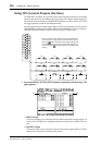
Using GPI (General Purpose Interface)
The DM1000’s CONTROL port provides a GPI (General Purpose Interface) for controlling
external equipment. You can configure the GPI so that it will output 8-channel trigger sig-
nals when you operate the faders or USER DEFINED KEYS, or so that it will receive 4-chan-
nel trigger signals to control the DM1000 parameters.
You can assign functions to these trigger signals. In this way, for example, you can control a
“RECORDING” warning light outside a studio from the DM1000, or you can control the
DM1000’s Talkback function or Dimmer function using an outside switch.
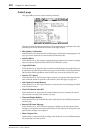
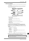
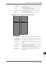
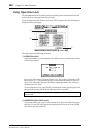
1 Press the DISPLAY ACCESS [SETUP] button repeatedly until the Setup | GPI
page appears.
A INPUT section
This section enables you to select functions that will be controlled via trigger signals 1–4
input at the CONTROL port. Assignable functions are listed in the area below this sec-
tion.
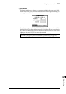
B OUTPUT section
This section enables you to select the sources that will output trigger signals 1–8. Select-
able sources are listed in the area below this section.
9 1 21 14 9 2 21 15
9 3 21 16 9 4 21 17
22 5 10 6
GPO0 GPO1 GPO2 GPO3
GPO4 GPO5 GPO6 GPO7
GPI0 GPI1
14
15
16
17
18
19
20
21
22
23
24
25
2
3
4
5
6
7
8
9
10
11
12
13
1
23 5 11 6
GPI2 GPI3
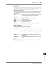
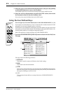
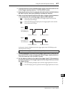
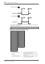
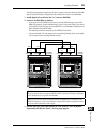
This is an example of the external circuit that operates GPI.
In this example, a trigger signal causes the LEDs to light up
when the button is selected as the trigger signal polarity
in the OUTPUT section. A trigger signal causes the LEDs to
turn off when the button is selected as the trigger signal
polarity.
21