


Output Patching 113
DM1000 Version 2—Owner’s Manual
9
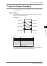
Input & Output Patching
Patching Omni Outs
You can route the DM1000’s internal signals to OMNI OUT 1–12.
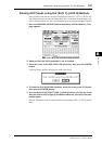
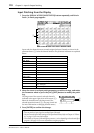
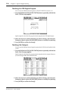
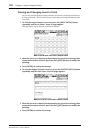
1 Press the DISPLAY ACCESS [OUTPUT PATCH] button repeatedly until the Out
Patch | Omni Out page appears.
The OMNI 1–12 parameter boxes (
1) indicate the currently-patched signals. The param-
eter indicators are explained below:
2 Move the cursor to a patch parameter you wish to change, and rotate the
Parameter wheel or press the [INC]/[DEC] buttons to modify the patching.
3 Press [ENTER] to confirm the change.
Parameter values Description
–
No assignment
BUS1–BUS8
Bus Out 1–8 signal
AUX1–AUX8
Aux Out 1–8 signal
ST L/R
Stereo Out signal
INS CH1–INS CH48
Input Channel 1–48 Insert Out
INS BUS1–INS BUS8
Bus Out 1–8 Insert Out
INS AUX1–INS AUX8
Aux Out 1–8 Insert Out
INS ST-L/ST-R
Stereo Out Insert Out
SURR XXX
(“XXX” represents a channel name.)
Surround Monitor Outs
CR-L/CR-R
Control Room Monitor signals
CAS BUS1–BUS8
Bus 1–8 Cascade Outs
CAS AUX1–AUX8
Aux Bus 1–8 Cascade Outs
CAS ST-L/ST-R
Stereo Bus Cascade Outs
CASSOLOL/CASSOLOR
Solo Bus Cascade Outs
SOLO-L/SOLO-R
Solo Bus signal
M.MX XXX
(“XXX” represents a channel name.)
Output signals from the surround monitor
monitor matrix
Tip: You can store the Output Patch settings to the Output Patch library. Refer to Chapter 15
“Libraries” on page 173 for more information.
1