


Input and Output Patching 51
DM1000 Version 2—Owner’s Manual
4
Connections and Setup
• SURR XXX
(“XXX” is a channel name). .............. Surround Monitor Outs
• CR-L/CR-R........................................... Control Room Monitor signals
• CAS BUS1–BUS8 ................................ Bus 1–8 Cascade Outs
• CAS AUX1–AUX8............................... Aux Send 1–8 Cascade Outs
• CAS ST-L/ST-R.................................... Stereo Bus Cascade Outs
• CASSOLOL/CASSOLOR ................... Solo Bus Cascade Outs
• SOLO-L/SOLO-R................................ Solo signals
• M.MX XXX
(“XXX” is a channel name.) .............. Surround Monitor Outs
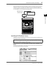
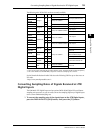
2 Use the cursor buttons to move the cursor to a patch parameter (
1) you
wish to change, and rotate the Parameter wheel or press the [INC]/[DEC]
buttons to modify the patching.
3 Press [ENTER] to confirm the change.
Tip: To restore the default patching, recall Output Patch memory #00 (see page 177).