


320 Appendix A: Parameter Lists
DM1000 Version 2—Owner’s Manual
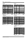
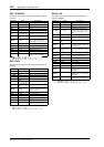
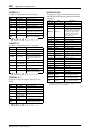
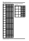
CHORUS 5.1
Six input, six output chorus for 5.1 surround.
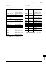
FLANGE 5.1
Six input, six output flanger for 5.1 surround.
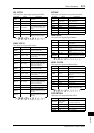
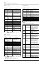
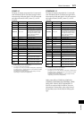
SYMPHO. 5.1
Six input, six output symphonic effect for 5.1 sur-
round.
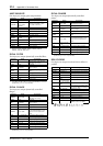
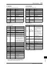
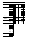
M.BAND DYNA.
Two input, two output 3-band dynamics processor,
with individual solo and gain reduction metering for
each band.
Parameter Range Description
FREQ. 0.05–40.00 Hz Modulation speed
AM DEPTH 0–100% Amplitude modulation depth
PM DEPTH 0–100% Pitch modulation depth
MOD. DLY 0.0–400.0 ms Modulation delay time
WAVE Sine, Tri Modulation waveform
HPF
THRU,
21.2 Hz–8.00 kHz
High-pass filter cutoff frequency
LPF
50.0 Hz–16.0 kHz,
THRU
Low-pass filter cutoff frequency
SYNC OFF, ON Tempo parameter sync on/off
NOTE
1
1.
Used in conjunction with
TEMPO to determine FREQ.
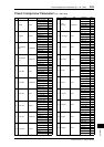
Parameter Range Description
FREQ. 0.05–40.00 Hz Modulation speed
DEPTH 0–100% Modulation depth
MOD. DLY 0.0–400.0 ms Modulation delay time
FB. GAIN –99 to +99%
Feedback gain (plus values for
normal-phase feedback, minus
values for reverse-phase feed-
back)
WAVE Sine, Tri Modulation waveform
HPF
THRU,
21.2 Hz–8.00 kHz
High-pass filter cutoff frequency
LPF
50.0 Hz–16.0 kHz,
THRU
Low-pass filter cutoff frequency
SYNC OFF, ON Tempo parameter sync on/off
NOTE
1
1.
Used in conjunction with
TEMPO to determine FREQ.
Parameter Range Description
FREQ. 0.05–40.00 Hz Modulation speed
DEPTH 0–100% Modulation depth
MOD. DLY 0.0–400.0 ms Modulation delay time
WAVE Sine, Tri Modulation waveform
HPF
THRU,
21.2 Hz–8.00 kHz
High-pass filter cutoff frequency
LPF
50.0 Hz–16.0 kHz,
THRU
Low-pass filter cutoff frequency
SYNC OFF, ON Tempo parameter sync on/off
NOTE
1
1.
Used in conjunction with
TEMPO to determine FREQ.
Parameter Range Description
LOW GAIN –96.0 to +12.0 dB Low band level
MID GAIN –96.0 to +12.0 dB Mid band level
HI. GAIN –96.0 to +12.0 dB High band level
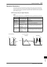
PRESENCE –10 to +10
For positive values, the threshold
of the high band is lowered and
the threshold of the low band is
increased. For negative values,
the opposite will occur. When
set to 0, all three bands are
affected the same.
CMP. THRE 24.0 to 0.0 dB Compressor threshold
CMP. RAT 1:1 to 20:1 Compressor ratio
CMP. ATK 0–120 ms Compressor attack
CMP. REL
1
Compressor release time
CMP. KNEE 0–5 Compressor knee
LOOKUP 0.0–100.0 ms Lookup delay
CMP. BYP OFF, ON Compressor bypass
L–M XOVR 21.2 Hz–8.00 kHz Low/mid crossover frequency
M–H XOVR 21.2 Hz–8.00 kHz Mid/high crossover frequency
SLOPE –6 to –12 dB Filter slope
CEILING
–6.0 to 0.0 dB,
OFF
Specifies the maximum output
level
EXP. THRE –54.0 to –24.0 dB Expander threshold
EXP. RAT 1:1 to ∞:1 Expander ratio
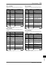
EXP. REL
1
1. 6 ms–46.0 s (fs=44.1 kHz), 5 ms–42.3 s (fs=48 kHz), 3 ms–23.0 s
(fs=88.2 kHz), 3 ms–21.1 s (fs=96 kHz)
Expander release time
EXP. BYP OFF, ON Expander bypass
LIM. THRE –12.0 to 0.0 dB Limiter threshold
LIM. ATK 0–120 ms Limiter attack
LIM. REL
1
Limiter release time
LIM. BYP OFF, ON Limiter bypass
LIM. KNEE 0–5 Limiter knee
SOLO LOW OFF, ON
If this is on, only the low-fre-
quency band will be output.
SOLO MID OFF, ON
If this is on, only the mid-fre-
quency band will be output.
SOLO
HIGH
OFF, ON
If this is on, only the high-fre-
quency band will be output.