


314 Appendix A: Parameter Lists
DM1000 Version 2—Owner’s Manual
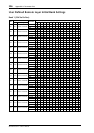
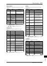
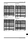
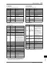
AMP SIMULATE
One input, two output guitar amp simulator.
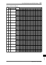
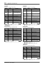
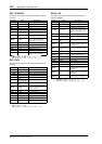
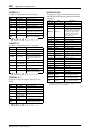
DYNA. FILTER
Two input, two output dynamically controlled filter.
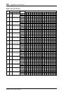
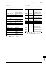
DYNA. FLANGE
Two input, two output dynamically controlled
flanger.
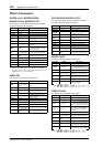
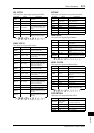
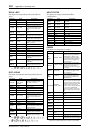
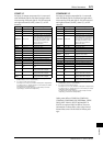
DYNA. PHASER
Two input, two output dynamically controlled
phaser.
REV+CHORUS
One input, two output reverb and chorus effects in
parallel.
Parameter Range Description
AMP TYPE
1
1. STK-M1, STK-M2, THRASH, MIDBST, CMB-PG, CMB-VR,
CMB-DX, CMB-TW, MINI, FLAT
Guitar amp simulation type
DST TYPE
DST1, DST2,
OVD1, OVD2,
CRUNCH
Distortion type (DST = distor-
tion, OVD = overdrive)
DRIVE 0–100 Distortion drive
MASTER 0–100 Master volume
BASS 0–100 Bass tone control
MIDDLE 0–100 Middle tone control
TREBLE 0–100 High tone control
CAB DEP 0–100%
Speaker cabinet simulation
depth
EQ F 100–8.00 kHz Parametric equalizer frequency
EQ G –12.0 to +12.0 dB Parametric equalizer gain
EQ Q 10.0–0.10 Parametric equalizer bandwidth
N. GATE 0–20 Noise reduction
Parameter Range Description
SOURCE INPUT, MIDI
Control source: input signal or
MIDI Note On velocity
SENSE 0–100 Sensitivity
DIR. UP, DOWN
Upward or downward fre-
quency change
DECAY
1
1. 6 ms–46.0 s (fs=44.1 kHz), 5 ms–42.3 s (fs=48 kHz), 3 ms–23.0 s
(fs=88.2 kHz), 3 ms–21.1 s (fs=96 kHz)
Filter frequency change decay
speed
TYPE LPF, HPF, BPF Filter type
OFFSET 0–100 Filter frequency offset
RESO. 0–20 Filter resonance
LEVEL 0–100 Output Level
Parameter Range Description
SOURCE INPUT, MIDI
Control source: input signal or
MIDI Note On velocity
SENSE 0–100 Sensitivity
DIR. UP, DOWN
Upward or downward fre-
quency change
DECAY
1
1. 6 ms–46.0 s (fs=44.1 kHz), 5 ms–42.3 s (fs=48 kHz), 3 ms–23.0 s
(fs=88.2 kHz), 3 ms–21.1 s (fs=96 kHz)
Decay speed
OFFSET 0–100 Delay time offset
FB.GAIN –99 to +99%
Feedback gain (plus values for
normal-phase feedback, minus
values for reverse-phase feed-
back)
LSH F 21.2 Hz–8.00 kHz Low shelving filter frequency
LSH G –12.0 to +12.0 dB Low shelving filter gain
EQ F 100 Hz–8.00 kHz EQ (peaking type) frequency
EQ G –12.0 to +12.0 dB EQ (peaking type) gain
EQ Q 10.0–0.10 EQ (peaking type) bandwidth
HSH F 50.0 Hz–16.0 kHz High shelving filter frequency
HSH G –12.0 to +12.0 dB High shelving filter gain
Parameter Range Description
SOURCE INPUT, MIDI
Control source: input signal or
MIDI Note On velocity
SENSE 0–100 Sensitivity
DIR. UP, DOWN
Upward or downward fre-
quency change
DECAY
1
1. 6 ms–46.0 s (fs=44.1 kHz), 5 ms–42.3 s (fs=48 kHz), 3 ms–23.0 s
(fs=88.2 kHz), 3 ms–21.1 s (fs=96 kHz)
Decay speed
OFFSET 0–100
Lowest phase-shifted frequency
offset
FB.GAIN –99 to +99%
Feedback gain (plus values for
normal-phase feedback, minus
values for reverse-phase feed-
back)
STAGE
2, 4, 6, 8, 10, 12,
14, 16
Number of phase shift stages
LSH F 21.2 Hz–8.00 kHz Low shelving filter frequency
LSH G –12.0 to +12.0 dB Low shelving filter gain
HSH F 50.0 Hz–16.0 kHz High shelving filter frequency
HSH G –12.0 to +12.0 dB High shelving filter gain
Parameter Range Description
REV TIME 0.3–99.0 s Reverb time
INI. DLY 0.0–500.0 ms Initial delay before reverb begins
HI. RATIO 0.1–1.0 High-frequency reverb time ratio
DIFF. 0–10 Spread
DENSITY 0–100% Reverb density
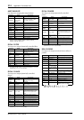
HPF
THRU,
21.2 Hz–8.00 kHz
High-pass filter cutoff frequency
LPF
50.0 Hz–16.0 kHz,
THRU
Low-pass filter cutoff frequency
REV/CHO 0–100%
Reverb and chorus balance (0%
= all reverb, 100% = all chorus)
FREQ. 0.05–40.00 Hz Modulation speed
AM DEPTH 0–100% Amplitude modulation depth
PM DEPTH 0–100% Pitch modulation depth
MOD. DLY 0.0–500.0 ms Modulation delay time
WAVE Sine, Tri Modulation waveform
SYNC OFF, ON Tempo parameter sync on/off
NOTE
1
1.
Used in conjunction with
TEMPO to determine FREQ.