


Aux Sends 93
DM1000 Version 2—Owner’s Manual
8
Aux Sends
8 Aux Sends
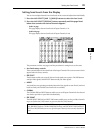
This chapter describes how to control Aux Out 1–8.
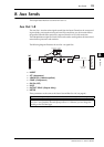
Aux Out 1–8
The Aux Out 1–8 section mixes signals routed from the Input Channels to the correspond-
ing Aux Sends, processes them using on-board EQ, compressor, etc., then routes them to
the specified internal effects processors, output connectors or I/O card connectors.
The DM1000 features eight Aux Sends, which can be used to send signals to the internal and
external effects processors and monitors.
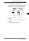
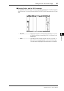
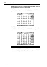
The following diagram illustrates the Aux Out 1–8 signal flow.
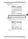
• INSERT
•ATT (Attenuator)
•4 BAND EQ (4-band equalizer)
• COMP (Compressor)
• ON (On/Off)
• LEVEL
• OUTPUT DELAY (Output delay)
• METER
These parameters are the same as the Stereo Out and Bus Out 1–8 (see page 81).
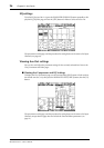
Tip: You can also pair adjacent odd-even Aux Sends (in this order) for stereo Aux operation.
Note: With the default setting, Aux Out 1–8 are patched to OMNI OUT connectors 1–8 and
Aux Out 1–4 are patched to internal effects processors 1–4. However, you can change this
patching on the Out Patch page.
OUTPUT PATCH
OUTPUT
DELAY
METER
ATT
4BAND
EQ
INSERT
INSERT
LEVEL
ON
COMP
METER
(Gain Reduction)
INSERT
METER
METER
(Out Meter)
TO INPUT PATCH
AUX 1(...8)
AUX 1(...8)
AUX 1
AUX 8