


110 Chapter 9—Input & Output Patching
DM1000 Version 2—Owner’s Manual
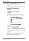
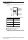
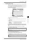
Input Patching from the Display
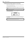
1 Press the DISPLAY ACCESS [INPUT PATCH] button repeatedly until the In
Patch | In Patch page appears.
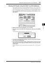
Inputs and slot channels that are currently assigned to Input Channels are shown in the
parameter boxes (
1) below the channel numbers. The parameter indicators are explained
below:
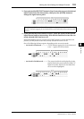
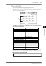
2 Move the cursor to an input patch parameter you wish to change, and rotate
the Parameter wheel or press the [INC]/[DEC] buttons to modify the patch-
ing.
The long name of the currently-selected channel is
indicated in the upper-right corner of the screen (
1).
Below the channel name is the long name of the
selected input/slot channel (
2). (See page 79 and 265
for more information on changing channel names.)
3 Press [ENTER] to confirm the change.
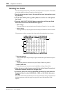
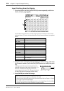
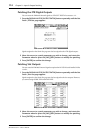
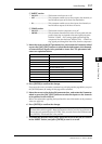
Parameter values Description
–
No assignment
AD1–AD16
INPUT connectors 1–16
OMN1–OMN4
OMNI IN connectors 1–4
S1-1–S116
Channels 1–16 of Slot 1
S2-1–S216
Channels 1–16 of Slot 2
FX1-1–FX1-8
Outputs 1–8 of Internal Effects Processor 1
FX2-1–FX2-2
Outputs 1 & 2 of Internal Effects Processor 2
FX3-1–FX3-2
Outputs 1 & 2 of Internal Effects Processor 3
FX4-1–FX4-2
Outputs 1 & 2 of Internal Effects Processor 4
2D1L & 2D1R
2TR DIGITAL IN 1 (L/R)
2D2L & 2D2R
2TR DIGITAL IN 2 (L/R)
BUS1–8
Bus 1–8 Outputs
AUX1–8
Aux 1–8 Outputs
Tip:
•You can patch an input signal to multiple Input Channels.
•You can store the Input Patch settings to the Input Patch library. Refer to Chapter 15 “Librar-
ies” on page 173 for more information.
• The number of outputs of internal Effects processor 1 varies depending on the selected effect
program. (See page 155 for more information on effect programs.)
1
1
2