


DA7 Users’ Guide
6
-
1
6
Fader Layers
Channel Strips
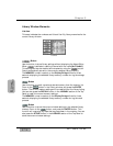
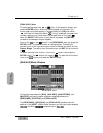
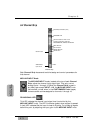
6-1 Fader Layers
The Fader Layer section is where you select the current function you want
to use for the Channel Strips. When you change layers, the DA7 updates the
fader positions to reflect the current status of the channel levels for that
layer. Any of the Channel Strips in that layer can now be edited.
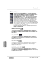
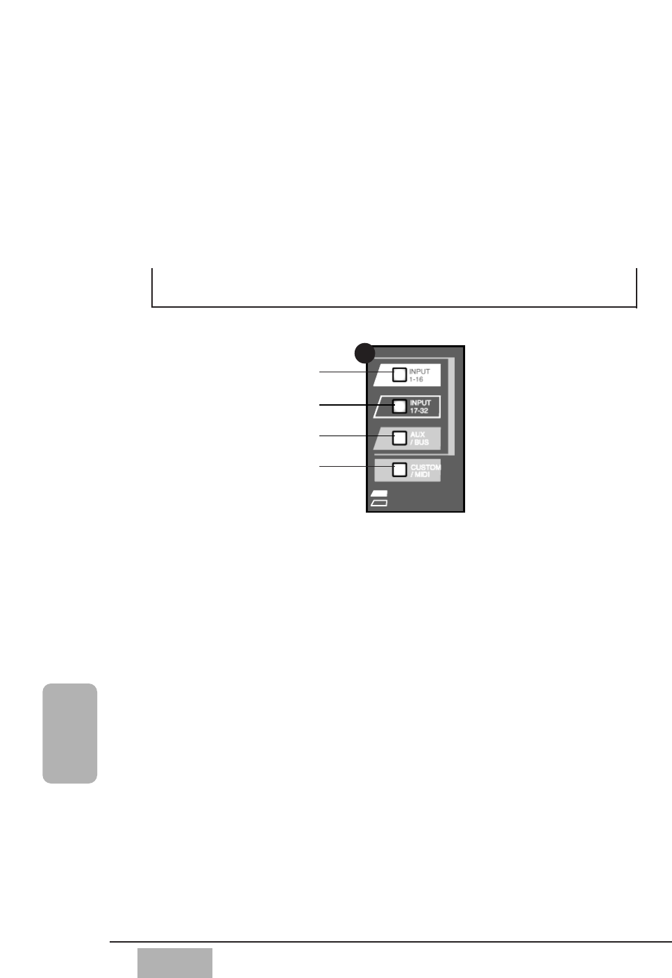
The INPUT 1-16 LED button when selected (green) controls analog inputs 1
through 16, and buses 1, 3, 5, and 7. The INPUT 17-32 LED button when
selected (red) controls inputs 17 through 32 (if there are audio option cards
installed), and buses 2, 4, 6, and 8. The AUX/BUS layer controls aux sends 1
through 6, aux returns 1 through 6, and buses 1 through 8, and has an
(orange) LED button. The CUSTOM/MIDI layer gives you a layer where all
functions are selectable from the [UTILITY>USER CSTM] (user custom)
window, and is also an (orange) LED button. One of these LED buttons
blinks when selected, if the FADER is set to off in the [UTILITY>CONFIG]
window.
For additional information on utility functions, see Chapter 16, Utility and
Solo Monitor.
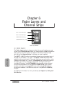
Chapter 6
Fader Layers and
Channel Strips
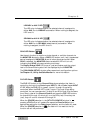
INPUT 1-16 LED button (green)
INPUT 17-32 LED button (red)
AUX/BUS LED button (orange)
CUSTOM/MIDI LED button (orange)
11
Fader Layer Section