Connections
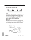
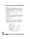
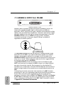
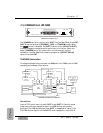
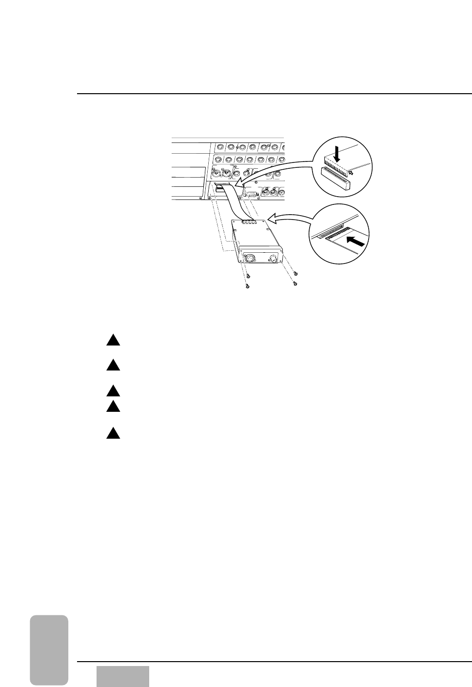
Please take the following steps to install the SMPTE/V SYNC card. See
illustration above.
Loosen the 4 screws, and then remove the blank panel of the SMPTE/V
SYNC slot.
Bend one end of the accessory cable of the WR-SMPT card, so that the
conductive surface becomes exposed as in the illustration.
Connect the bent end of the cable, as shown, to the DA7.
Connect the other end of the cable to the WR-SMPT, so that the
conductive surface is in the up position, as shown.
After making sure that the conductive surface of the accessory cable is
facing up, insert the card carefully and fasten the 4 removed screws.
Chapter 17
DA7 Users’ Guide
17
-
10
17
Options
WR-SMPT
1
2
3
4
5


