


Chapter 2
DA7 Users’ Guide
2
-
29
2
DA7 Tour
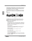
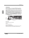
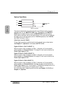
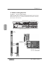
Format Select Switch
This switch is used to select the signal format of the Digital Record Output,
either AES/EBU (RS-422/110Ω) or S/PDIF (0.5 V[p-p]/ 75Ω) physically. The
status information included in the output signals is always “professional”
regardless of the switch position.
For S/PDIF usage, an optional adapter is required(Part No. DA/ADPTF). You
must make certain that the adapter connects pin #1 and #3 together.
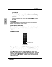
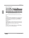
Clock Terminating 75 ½ ON/OFF & Out / Thru Switch
Located next to the WORD CLOCK IN BNC connection, this switch should
be set to 75 Ω OFF and Thru position if the DA7 is being used to pass the
wordclock signal to other devices in the chain.
Set the switch to 75 Ω ON and OUT for terminating the wordclock, if the
DA7 is slaved and located at the end of the wordclock chain. The 75 Ω ON
and OUT position should also be selected when the DA7 is being used to
slave other devices to the DA7’s wordclock. See Chapter 12, D-I/O for more
information.
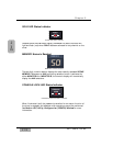
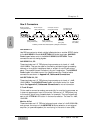
Clock Input
This is used to synchronize the DA7 to an external wordclock source. This
allows the DA7’s internal clock to slave to another reference, such as a digital
multi-track deck or other device. Use a BNC connector to attach an external
wordclock source.
Clock Output
This is used to slave an external device, such as a digital multi-track machine,
to the DA7 internal clock. It can also be used to relay an external wordclock
that is being used to synchronize the DA7 to an external device. Using a BNC
connector, other devices can synchronize to the DA7 wordclock.
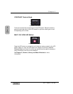
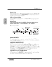
Serial Terminating Switch
Set the switch to ON if the DA7 is the termination point of the RS-422/485
serial transmission path. The 110Ω switch turns this function OFF/ON.