


Chapter 6
DA7 Users’ Guide
6
-
3
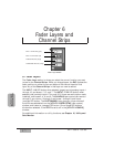
6
Fader Layers
Channel Strips
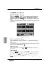
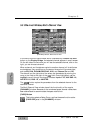
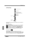
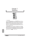
6-2 Channel Strip
Each Channel Strip has several tools that assign and control parameters for
that channel.
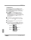
MIC/LINE INPUT Knob
The MIC/LINE INPUT knobs, located at the top of each Channel
Strip, adjust the channel input signal level. They only control
analog inputs 1 through 16. When the Channel Strip is used in
any fader layer except INPUT 1-16, the MIC/LINE INPUT knob
has no effect, unless, when in the CUSTOM/MIDI Fader Layer,
there are audio sources assigned to channels 1 through 16.
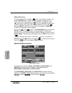
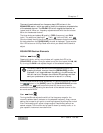
PEAK/SIGNAL LED
This LED indicates the channel input signal level (controlled by the
MIC/LINE INPUT knob). The LED illuminates (green) when a signal is sensed.
A (red) LED indicates that the input is close to clipping. Try to keep all signals
below this point by adjusting the input gain via the MIC/LINE INPUT knob.
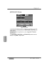
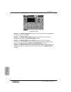
Channel Strip
Fader
MIC/LINE input attenuator (knob)
PEAK/SIGNAL LED
LED field indicators for AUX 1-6 and
automation parameters: CH ON, EQ,
PAN/ASSIGN/SURR, LIBRARY, and SEL/MAN
SOLO LED button
FLIP LED button
SELECT LED button
ON LED button
Channel number
AUX/BUS Fader
Layer function