


Chapter 2
DA7 Users’ Guide
2
-
13
2
DA7 Tour
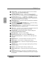
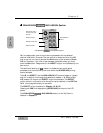
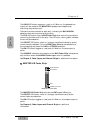
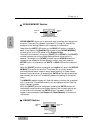
The SOLO LED button toggles on (red) or off. When on, the selected bus
output will be routed to the MONITOR A speakers and headphones,
overriding the previous input.
There are two bus numbers for each strip, indicating the BUS ASSIGN
selections that can be controlled by the strip.
The FLIP LED button flips the BUS Fader Strip from controlling one bus to
controlling the other bus for the strip. The LED color (red or green) indicates
the current bus selection.
The SELECT LED button, when on (orange), identifies the bus strip as the
current bus strip selected. Only one BUS Fader Strip can be selected at a
time unless they are paired for LINK or STEREO operation.
The ON LED button toggles on (red) and off. When on, the bus output is
active.
The AUX/BUS indication at the bottom of the BUS Fader Strip indicates the
strip function when the AUX/BUS Fader Layer control is selected.
See Chapter 6, Fader Layers and Channel Strips for additional information.
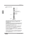
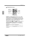
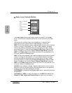
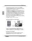
MASTER L/R Fader Strip
The MASTER L/R Fader Strip controls the DA7 master L/R output.
The SELECT LED button, when on (orange), identifies the strip as the
current fader strip selection.
The ON LED button toggles on (red) and off. When on, the master output is
active.
See Chapter 6, Fader Layers and Channel Strips for additional
information.
Fader
AUX/BUS Layer function
SELECT LED button
ON LED button
10
MASTER L/R Fader Strip