


Chapter 2
DA7 Users’ Guide
2
-
5
2
DA7 Tour
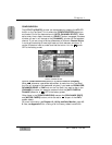
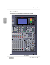
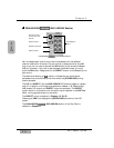
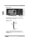
Channel Strip – input gain controls with channel control and status
indicators. Also called a Channel Fader Strip.
AUTOMATION/AUX LED button – selects the display mode of the
Channel Strip LED field indicators, and arms the AUTOMATION system.
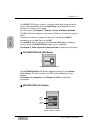
MASTER DISPLAY section – the METER and CHANNEL buttons are
direct buttons to the respective LCD screen windows. These should be
considered "home base" for the LCD display.
EQUALIZER section – controls for setting the equalization parameters
for a selected channel.
PAN/ASSIGN/ , BUS ASSIGN section – controls for setting
the pan and bus assignments for a selected channel.
DYNAMICS/DELAY section – controls for setting the onboard dynamics
processing parameters for a selected channel.
AUX section – controls for routing channels to outboard sources and for
defining the signal path as either pre-fader or post-fader.
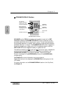
Display Bridge – contains the LCD screen, L/R meter display, and
primary mixer display status indicators.
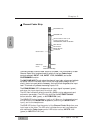
BUS Fader Strip – controls for output BUSes.
MASTER L/R Fader Strip – controls for L/R MASTER output.
Fader Layer Controls section – selects the current fader layer to be
displayed.
MONITOR section – volume and selection controls for monitoring.
SETUP section – mixer function, or display control buttons.
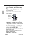
SCENE MEMORY section – buttons for writing and reading the 50 mixer
scene memories.
LIBRARY section – buttons for storing and recalling Channel, EQ and
Dynamics libraries.
Keypad – alphanumeric keys for entering numbers or text.
Cursor Control section – buttons and controls for defining the cursor
actions.
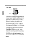
Headset Control section – the location of the headset connector and
the level control of the DA7 is immediately below the right front edge of
the Top Panel.
10
11
12
13
14
15
16
17
18
1
2
3
4
5
6
7
8
9