


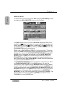
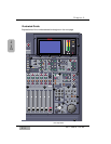
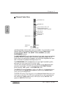
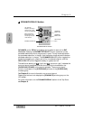

Channel Fader Strip
There are sixteen Channel Fader Strips on the DA7. The functionality of each
Channel Fader Strip is determined by which of the four Fader Layer
controls selected: INPUT 1-16, INPUT 17-32, AUX/BUS, and a user
CUSTOM/MIDI function.
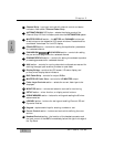
The MIC/LINE INPUT knob varies the channel input gain volume and adjusts
for either a mic or line-level input. Due to the high quality design of this
circuit, there is no pad switch necessary; the input knob range sets the input
level. This knob only affects the analog inputs 1-16.
The PEAK/SIGNAL LED indicates when an input signal is present (green),
and when the input signal level is too high (red).
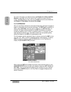
The LED field indicators reflect the auxiliary (AUX) routing assignments and
automation parameters. The LED color signifies the AUTOMATION/AUX
button selection, AUX (green), or AUTOMATION (red).
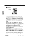
The SOLO LED button toggles on (red) or off. When on, the channel output
will be routed to the MONITOR A speakers (overriding the MONITOR A
input), and to the headphones.
The FLIP LED button flips the control of the Channel Fader Strip from one
input layer to the other. The LED color indicates the current input selection
and matches the Fader Layer control LED button colors, INPUTS 1-16
(green) or INPUTS 17-32 (red).
Chapter 2
DA7 Users’ Guide
2
-
6
2
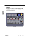
DA7 Tour
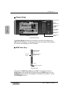
Fader
MIC/LINE INPUT knob
PEAK/SIGNAL LED
LED field indicators for AUX 1-6, and
automation parameters, CH, EQ,
PANASSIGN/SURR, LIBRARY and SEL/MAN
SOLO LED button
FLIP LED button
SELECT LED button
On LED button
Channel Fader Strip
Channel numbers
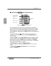
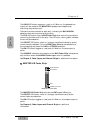
AUX/BUS Layer
function
1