


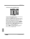

Connections
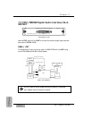
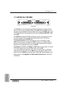
Insert two optional ADAT cards into SLOT 1 and SLOT 2. Carefully screw
these cards into their respective slots in the DA7 so they are properly
grounded. Each ADAT machine is connected to an option card via two optical
cables, one In and one Out. The 8-track ADAT signal in SLOT 1 is assigned to
inputs 17-24, and the 8-track ADAT signal in SLOT 2 is assigned to inputs 25-
32.
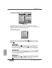
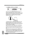
The output sources into the ADAT can be selected from the [D-I/O>SLOT
OUT] window.
Refer to Chapter 12, D-I/O for additional information.
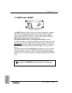
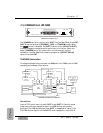
Wordclock Setup
The Word Clock master for this example is an Alesis BRC and the ID setting
must be set to zero. Both ADATs and the DA7 operate as slaves to the BRC.
The wordclock signal from the "WC OUT" of the BRC connects to the WORD
CLOCK IN of the DA7 Rear Panel. Set the terminate switch on the DA7 to
on.
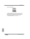
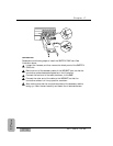
The DA7 clock must be set from the [D-I/O>INPUT SET] window by
selecting [WCK IN].
Chapter 17
DA7 Users’ Guide
17
-
4
17
Options