


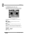
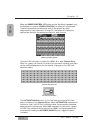
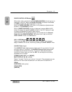

FADER CONTROL LED Button
When active (red), a window from the [FADER CONTROL] window group is
displayed in the LCD. When the FADER CONTROL LED button is activated,
the [AUX] window last used is displayed on the LCD.
When the FADER CONTROL LED button is off, parameter adjustments can
be seen in the [CHANNEL] window.
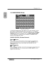
When a [FADER CONTROL] window is displayed, press an AUX 1-6 LED
button to display the respective [AUX] window in the LCD. Faders will react
to display the selected aux send for each channel.
Level adjustments for the selected channel can be made with the Channel
Fader when the FADER CONTROL LED button is on (red), or with the
LEVEL ON/OFF knob in the AUX section.
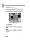
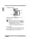
AUX 1-6 LED Buttons
, , , , ,
Press one of the AUX 1-6 LED buttons to select it (green). Once selected,
assign the AUX to the current channel by pressing the LEVEL ON/OFF knob.
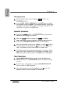
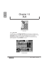
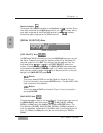
AUX/BUS Fader Layer
The AUX/BUS Fader Layer gives you fader control for aux sends 1 through
6 and aux returns 1 through 6. The AUX/BUS Channel Strip designations
are labeled at the bottom of the strip. The first six faders are the output
controls for the aux send mix from the DA7. You can adjust the following
parameters for aux sends:
[STEREO] [ON], [OFF], and [MONO].
[MUTE GRP] [1], [2], [3], and [4]
Faders 7 through 12 are for aux returns 1 through 6. The parameters you can
adjust for aux returns are the same as in aux sends, with the addition of:
[GAIN]
[FADR GRP] (fader group)
[EQUALIZER]
[ASSIGN]
Chapter 10
DA7 Users’ Guide
10
-
4
10
AUX