


Chapter 17
DA7 Users’ Guide
17
-
6
17
Options
Connections
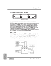
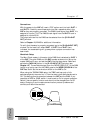
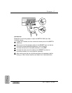
With the power to the DA7 off, insert a TDIF option card into both SLOT 1
and SLOT 2. Carefully screw these cards into their respective slots in the
DA7 so they are properly grounded. The DA88 8-track signal from SLOT 1 is
assigned to inputs 17-24. The DA88 8-track signal from the SLOT 2 card is
assigned to inputs 25-32.
The output sources into the DA88 can be selected from the [D-I/O>SLOT
OUT] window.
Refer to Chapter 12, D-I/O for additional information.
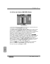
To verify that the setup is properly connected, go to the [D-I/O>INPUT SET]
window. On the lower left, where SLOT 1, SLOT 2, and SLOT 3 are
indicated, the crosshatching will go away when a proper connection has
been made.
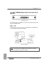
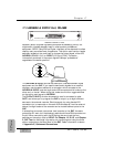
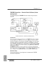
Wordclock Setup
The Word Clock master in this setup is the DA88 that is attached to SLOT 1
of the DA7. The other DA88 and the DA7 operate as slave units. Set up the
master DA88 as ID zero, and set the DA7 to be the slave device. Select and
activate the [WCK IN] button in the [D-I/O INPUT SET] window (see
Chapter 12). The wordclock signal from the "WORD SYNC OUT" of the SY88
(which is an option card for the DA88) goes to the WORD CLOCK IN of the
DA7 Rear Panel. Set the termination switch on the DA7 to On.
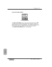
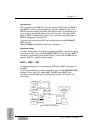
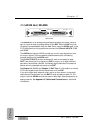
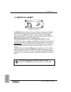
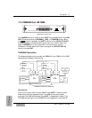
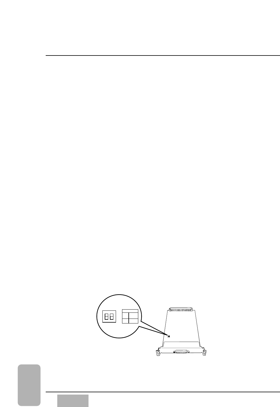
When using the TASCAM DA88 setup, the TDIF card has a pair of dip
switches physically mounted on it. From the factory both switches are set to
Off. This setting permits operation between the DA7 and the DA88. If you
use either a DA38 or DA98, switch 1 must be set to On for proper operation.
Switch 2 has no specific function and should not be changed from its Off
status. Changing it could create communication protocol problems and
conflicts, and should be avoided.
DIP SW
DIP SW
ON
ON
OFF
OFF
1 2
DA38
DA98
DA88
WR-TDIF