


109
CHAPTER 8 FUNCTIONS
8
8.2 Cyclic Transmission
8.2.3 Assurance of cyclic data integrity
(3) Interlock program
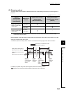
Data of more than 32 bits can be assured with the Block Data Assurance per Station setting disabled. Use either
of the following methods.
• Interlock using X and Y
• Interlock using devices other than X and Y (when X, Y cannot be used as an interlock device)
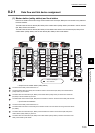
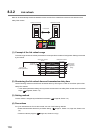
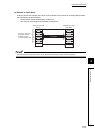
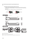
(a) Example of interlock using X and Y
An example of sending data in W0 to W3 of the master station (safety station) (station No. 0) to W600 to W603
of the local station (station No. 1) is shown below. (X1000 and Y1000 are used for a handshake to the safety
CPU modules of RX and RY.)
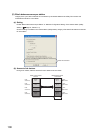
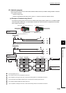
The send request turns on.
The contents of D0 to D3 are transferred to W0 to W3.
Upon completion of storage in W0 to W3, Y1000 at the sending station for a handshake is turned on.
Cyclic transmission sends RWw followed by RY, and X1000 of the receiving station turns on.
The contents of W600 to W603 are stored in D0 to D3.
Upon completion of storage in D0 to D3, Y1000 at the receiving station for a handshake is turned on.
1
4 5
2
3
7
6
8
Cyclic transmission
Link refresh
Data flow
Program
Send
request
SET Y1000
X1000
Y1000
RX0
RY0RY0
RWw0
RWr0
RWw0
RWr0
RX0
Y1000
W0
W600
W0
W600
X1000
Safety CPU
module
Master station
(safety station)
Safety CPU
module
Master/local module
Local
station
Master/local module
Receiving stationSending station
Send data (W) Receive data (W)
X1000
Master station (safety station) (Station No. 0)
Master station (safety station) (Station No. 0)
Local station (Station No. 1)
Local station (Station No. 1)
Sending station
Receiving station
1
2
3
4
5
6