


75
CHAPTER 6 INSTALLATION AND WIRING
6
6.4 Tests After Wiring
6.4.3 Communication test
6.4.3 Communication test
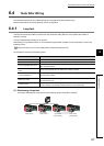
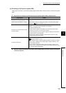
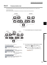
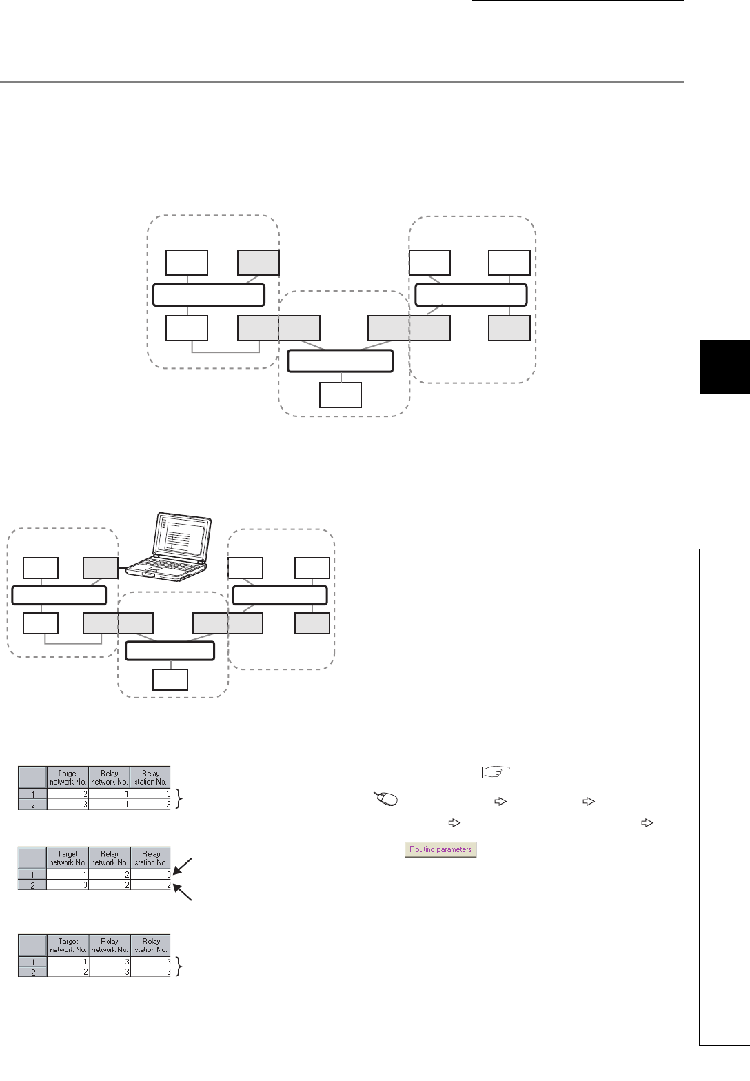
Communication test checks if transient transmission data can be properly routed from the own station to the
communication target.
Take the following system configuration as an example of communication test procedure.
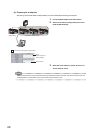
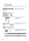
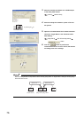
1. Connect GX Developer to the safety CPU module.
2. Set routing parameters in GX Develoepr as shown in
the figure to left. ( Page 92, Section 7.7)
Project data list [Parameter] [Network
param] [Ethernet/CC IE/MELSECNET]
button
Communication
target
Own station
(request source)
CC-Link IE
Field Network
CC-Link IE
Field Network
CC-Link IE
Field Network
Station
No. 2
Station
No. 1
Station
No. 3
Station
No. 0
Station
No. 0
Station
No. 2
Station
No. 4
Station
No. 0
(Relay
station 1)
Station
No. 2
Station
No. 3
(Relay
station 2)
Station
No. 1
Network No. 1 Network No. 3
Network No. 2
GX Developer
Communication
target
Own station
(request source)
CC-Link IE
Field Network
CC-Link IE
Field Network
CC-Link IE
Field Network
Station
No. 2
Station
No. 1
Station
No. 3
Station
No. 0
Station
No. 0
Station
No. 2
Station
No. 4
Station
No. 0
(Relay
station 1)
Station
No. 2
Station
No. 3
(Relay
station 2)
Station
No. 1
Network No. 1 Network No. 3
Network No. 2
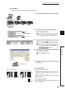
Routing parameters for stations of network No. 1
No setting is required for station
No. 3 because data are transmitted
via the station itself.
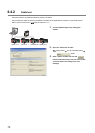
Routing parameters for stations of network No. 2
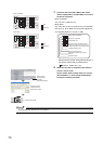
Routing parameters for stations of network No. 3
No setting is required for station
No. 3 because data are transmitted
via the station itself.
No setting is required for station
No. 0 because data are transmitted
via the station itself.
No setting is required for station
No. 2 because data are transmitted
via the station itself.