


240
If the above actions do not solve the problem, perform the following tests on the master/local module to check for an
error.
• Hardware test ( Page 60, Section 6.2.1)
• Self-loopback test ( Page 62, Section 6.2.2)
• Loop test ( Page 67, Section 6.4.1)
• Cable test ( Page 74, Section 6.4.2)
(4) The ERR. LED turns on
Connect GX Developer to the safety CPU module mounted with the master/local station whose ERR. LED is on,
identify the cause of the error, and take action. (
Page 235, Section 12.2)
If the cause of the error cannot be identified using GX Developer, perform the following tests to the master/local
module to check for hardware error.
• Hardware test ( Page 60, Section 6.2.1)
• Self-loopback test ( Page 62, Section 6.2.2)
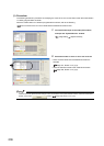
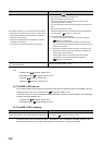
(5) The ERR. LED is flashing
If the above action does not solve the problem, "Total Stations" set in the Network Parameter window for the
master station differs from the number of slave stations on the network. Correct the parameter.
Check that the cables are not connected as described below.
• Both PORT1 and PORT2 are connected to a switching hub.
• Although the loopback function is disabled, the network is
configured in ring topology.
• Although the loopback function is enabled, the network is
configured in star topology.
• The network is incorrectly configured in ring topology.
• Correct the wiring. ( Page 47, Section 5.1.1)
• If the system does not contain a switching hub
• If the system contains a switching hub
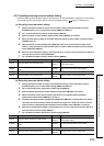
Is the station number of the master/local module duplicated with
any of the other stations?
Change the duplicated station number.
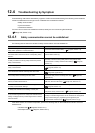
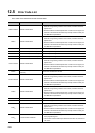
Check item Action
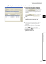
Is the disconnected station displayed in the network
configuration diagram of CC-Link IE Field Network diagnostics?
Perform the troubleshooting shown in "When the D LINK LED turned off
or is flashing". ( Page 239, Section 12.3 (3))
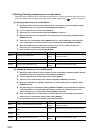
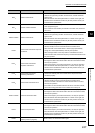
Check item Action
• When not using the loopback function
Disconnect an Ethernet cable connected to any station on the
network (either PORT1 or PORT2).
The network topology will become a line topology and data link will
start.
• When using the loopback function
Enable the loopback function and rewrite the network parameter to
the CPU module. ( Page 121, Section 8.6)
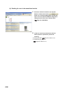
1. Check if the loopback function setting is correctly configured.
( Page 121, Section 8.6)
If incorrect, correct the network parameter and rewrite it to the
CPU module. When data link starts across the entire network, this
procedure is successful.
2. Disconnect one Ethernet cable connected to the switching hub
and power off and then on the hub. (Repeat this operation until
data link starts over the network.)
3. When data link starts over the network, check the network
configuration by CC-Link IE Field Network diagnostics.
( Page 124, CHAPTER 9)