


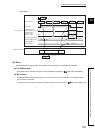

195
CHAPTER 10 DEDICATED INSTRUCTIONS
10
10.8 JP/GP.REQ (Reading/Writing Clock Data)
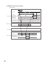
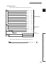
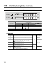
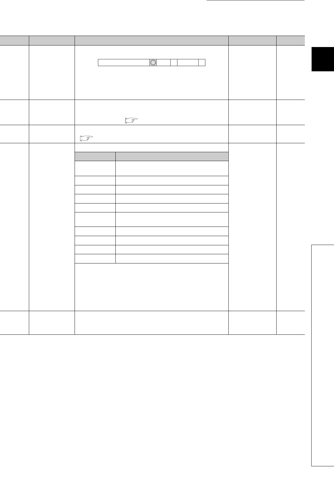
(a) Control data
Device Item Setting data Setting range Set by
(S1)+0
Abnormal end
type
1) Abnormal end type (bit 7)
Specify the set status of data in case of abnormal end.
0: After (S1)+11, no data is set for abnormal end
1: After (S1)+11, data is set for abnormal end
0011
H
0091
H
User
(S1)+1 Completion status
The status of the instruction completion is stored.
0: Normal
Other than 0: Error ( Page 246, Section 12.5)
System
(S1)+2
Channels used by
own station
Specify the channels to be used by the own station.
( Page 155, Section 10.2.1 (3))
1 to 2 User
(S1)+3
Target station's
CPU type
Specify the CPU module on the station to be accessed.
0000
H
03D0
H
to 03D3
H
03E0
H
to 03E3
H
03FF
H
User
Set value Description
0000
H
Control CPU (The access destination is the same as that
of when 03FF
H
is selected.)
03D0
H
Control system CPU (redundant CPU only)
03D1
H
Standby system CPU (redundant CPU only)
03D2
H
System A CPU (redundant CPU only)
03D3
H
System B CPU (redundant CPU only)
03E0
H
• Control CPU (single CPU system)
• CPU No.1 (multiple CPU system)
03E1
H
CPU No.2 (multiple CPU system)
03E2
H
CPU No.3 (multiple CPU system)
03E3
H
CPU No.4 (multiple CPU system)
03FF
H
Control CPU
When the instruction is executed by specifying a control system CPU
(03D0
H
) or standby system CPU (03D1
H
), if system switching occurs
in the target station, the instruction may fail (CPU module error code:
4244
H
, 4248
H
).
If the above error occurs and the instruction fails, execute the
instruction again.
(S1)+4
Target station's
network No.
Specify the network No. of the target station.
1 to 239: Network No.
254: Specify this when 254 is set for Jn.
1 to 239
254
User
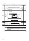
b15
000111
b7 b4 b0to to to