166
(4) Program example
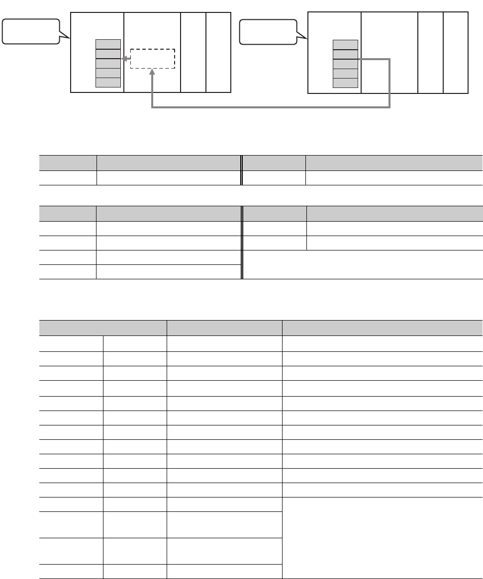
The following program is for reading data of D250 to D254 of station No. 4 (target station) into D700 to D704 of
station No. 0 (own station) when M101 is turned on.
(a) System configuration example
(b) Devices used in the program example
• Link special relay (SB), link special register (SW)
• Devices used by the user
(c) READ instruction setting
The setting of READ instruction control data is as follows.
Device Description Device Description
SB0047 Baton pass status (own station) SW00A0.3 Baton pass status (each station) of station No. 4
Device Description Device Description
M100 Control data setting command D200 to D217 Control data
M101 Start contact D700 to D704 Read data storage device (station No. 0)
M105 Completion device
M106 Completion status indication device
Device Item Set value
(S1)+0 D200 Abnormal end type
0081
H
(Sets data for abnormal end)
(S1)+1 D201 Completion status (Setting is not required because it is set by the system)
(S1)+2 D202 Channels used by own station 1
(S1)+3 D203 Target station's CPU type
0000
H
(control CPU)
(S1)+4 D204 Target station's network No. 1
(S1)+5 D205 Target station number 4
(S1)+6 D206 (Unused) 0
(S1)+7 D207 Number of resends 5 times
(S1)+8 D208 Arrival monitoring time 0 (10 seconds)
(S1)+9 D209 Read data length 5 words
(S1)+10 D210 (Unused) 0
(S1)+11 D211 Clock set flag
(Setting is not required because it is set by the system)
(S1)+12 to
(S1)+15
D212 to D215 Clock data of abnormal end
(S1)+16 D216
Error-detected station's
network No.
(S1)+17 D217 Error-detected station number
Safety CPU module
READ instruction
request source
(Own station)
READ instruction
request target
(Target station)
D700
D701
D702
D703
D704
D250
D251
D252
D253
D254
Master/local
module
Master/local
module
Channel 1
Safety CPU module
Network No. 1
Station No. 0 Station No. 4


