


97
CHAPTER 8 FUNCTIONS
8
8.1 Safety Communication Function
8.1.1 Communication with safety stations
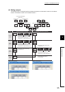
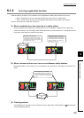
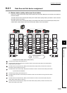
(1) Safety communication flow
After a safety connection is established, safety data is sent periodically from safety stations on both stations.
The device status in the safety CPU module on a station (sending side) is stored into a device in the safety CPU
module on the other station (receiving side). The figure below is an example of safety communication between a
master station (safety station) and a local station (safety station). Safety communication between local stations
(safety station) is also the same.
• Output from a master station (safety station)
• Output from a local station (safety station)
The device in the safety CPU module on a master station (safety station) turns on.
The device status in the safety CPU module on the master station (safety station) is stored into the
device in the safety CPU module on the local station (safety station) by safety data transfer.
The device in the safety CPU module on a local station (safety station) turns on.
The device status in the safety CPU module on the local station (safety station) is stored into the
device in the safety CPU module on the master station (safety station) by safety data transfer.
2
1 3
4
Master
station
(safety station)
Local
station
(safety station)
Safety CPU
module
Device
ENDENDEND
Device
Sequence
scan
M0
Y
Station No. 0
Safety CPU
module
Device
Device
Sequence
scan
ENDENDEND
M0
Y
Station No. 1
Safety connection
establishment
Safety data transfer
Safety data transfer
1
2
3
4