


303
APPENDICES
A
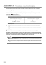
Appendix 5 Processing Time
Appendix 5.2 Link scan time
Appendix 5.2 Link scan time
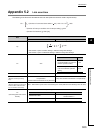
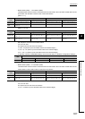
The following is the formula to calculate the link scan time (when the link scan mode is asynchronous).
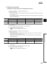
Item
Cyclic transmission mode
Normal mode High speed mode
Np
α: Total number of points of "RX/RY Setting" in "Network Configuration Settings"
β: Total number of points of "RWw/RWr Setting" in "Network Configuration Settings"
Ka 25.8
Kb 655 168
Kc
(Maximum transient processing
time)
160 + 60 × Total number of slave stations set in
the parameters
(0 when transient transmission is not performed)
80 (0 when transient transmission is not performed)
Kd
(Maximum data link processing time
when the station is disconnected
from or returned to the network)
9000 + Total number of ports used in the switching hub × 3000 (9000 when the switching hub is not used)
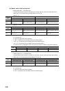
Ke
(Processing time factor of each
module)
The table below shows the processing time factor of each module. Add values of all stations.
+ (Number of connected slave stations Ka) + Kb + Kc + Kd
1000
+ (Number of interrupt conditions in the interrupt setting) 0.02
+ (Ke total of all stations) 1000 [ms]
LS = N
P
0.08
+
4
4
Conditions Value
When "Turn OFF or 0 Clear
Input Data (RX/RY)" is set in the
Network Operation Setting
18.5
When "Hold input data (RX/RY)"
is set in the Network Operation
Setting
9.75
Module Value
Master/local module
Safety station: 300
Standard station: 0
Other than master/local module 0