


40
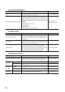
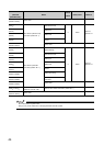
3.4 List of I/O Signals
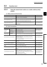
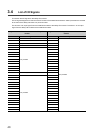
This section lists I/O signals for the safety CPU module.
The I/O signal assignment of when the start I/O number of the master/local module is "0000" (the module is mounted
to the 0 slot of the safety main base unit) is shown below.
The device X is an input signal from the master/local module to the safety CPU module. The device Y is an output
signal from the safety CPU module to the master/local module.
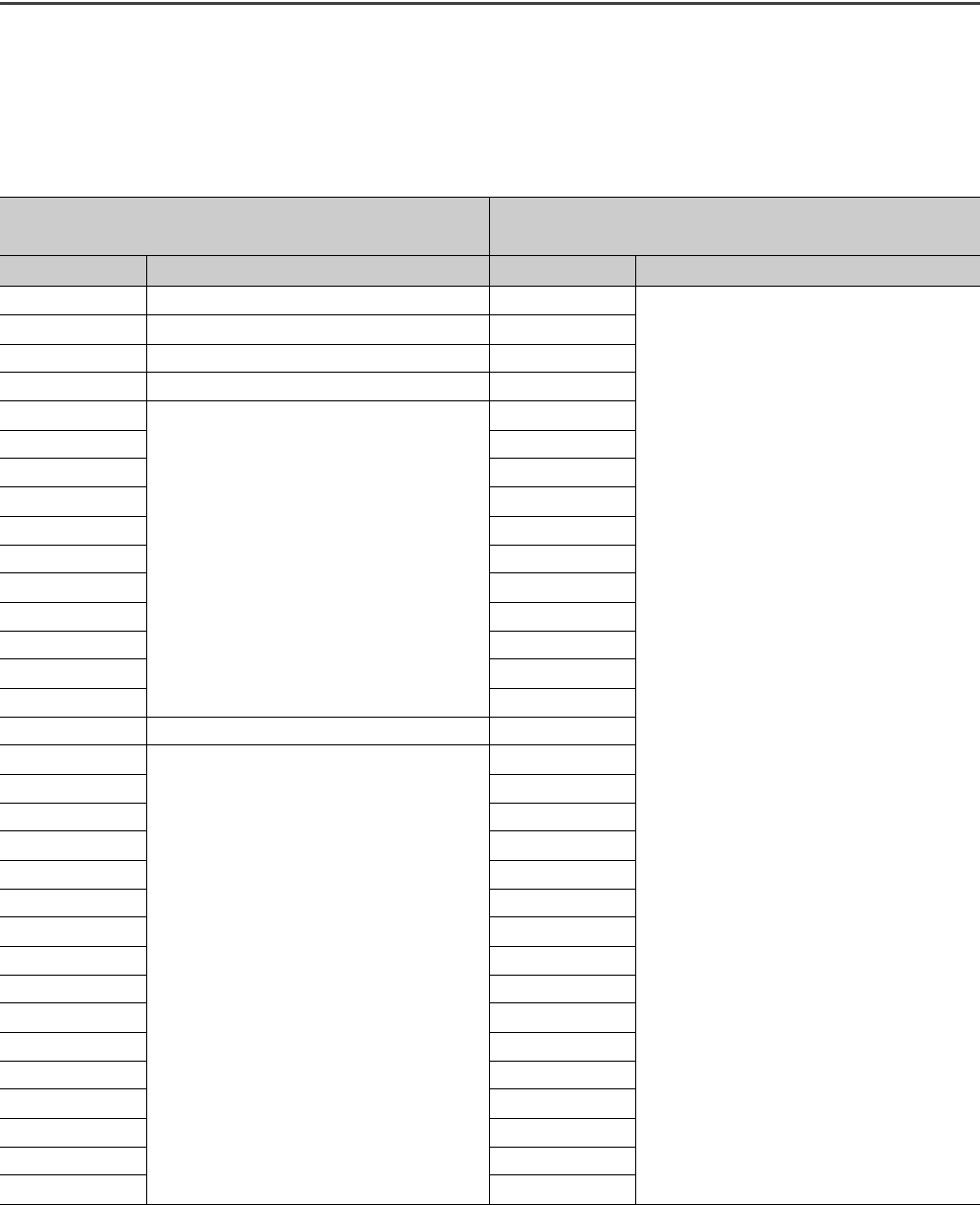
Signal direction: Master/local module Safety CPU
module
Signal direction: Safety CPU module Master/local
module
Device number Signal name Device number Signal name
X0 Module failure Y0
Use prohibited
X1 Own station data link status Y1
X2 Use prohibited Y2
X3 Other stations data link status Y3
X4
Use prohibited
Y4
X5 Y5
X6 Y6
X7 Y7
X8 Y8
X9 Y9
XA YA
XB YB
XC YC
XD YD
XE YE
XF Module ready YF
X10
Use prohibited
Y10
X11 Y11
X12 Y12
X13 Y13
X14 Y14
X15 Y15
X16 Y16
X17 Y17
X18 Y18
X19 Y19
X1A Y1A
X1B Y1B
X1C Y1C
X1D Y1D
X1E Y1E
X1F Y1F