


12
10.3 Understanding the Documentation on Dedicated Instructions . . . . . . . . . . . . . . . . . . . . . . . .158
10.4 JP/GP.READ (Reading Data from the Programmable Controller on Another Station) . . . . . .160
10.5 JP/GP.SREAD (Reading Data from the Programmable Controller on Another Station). . . . .168
10.6 JP/GP.WRITE (Writing Data to the Programmable Controller on Another Station) . . . . . . . .175
10.7 JP/GP.SWRITE (Writing Data to the Programmable Controller on Another Station) . . . . . . .187
10.8 JP/GP.REQ (Reading/Writing Clock Data) . . . . . . . . . . . . . . . . . . . . . . . . . . . . . . . . . . . . . . .194
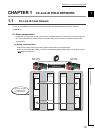
CHAPTER 11 PROGRAMMING 209
11.1 Precautions for Programming. . . . . . . . . . . . . . . . . . . . . . . . . . . . . . . . . . . . . . . . . . . . . . . . .209
11.2 Communication Example of when Safety Stations and a Standard Station are Used . . . . . .211
11.2.1 System configuration example. . . . . . . . . . . . . . . . . . . . . . . . . . . . . . . . . . . . . . . . . . . . . . . 211
11.2.2 Master station (standard station) settings . . . . . . . . . . . . . . . . . . . . . . . . . . . . . . . . . . . . . . 213
11.2.3 Local station (safety station) settings. . . . . . . . . . . . . . . . . . . . . . . . . . . . . . . . . . . . . . . . . . 215
11.2.4 Checking the network status . . . . . . . . . . . . . . . . . . . . . . . . . . . . . . . . . . . . . . . . . . . . . . . . 218
11.2.5 Program example. . . . . . . . . . . . . . . . . . . . . . . . . . . . . . . . . . . . . . . . . . . . . . . . . . . . . . . . . 219
11.3 Using Link Special Relay (SB) and Link Special Register (SW) . . . . . . . . . . . . . . . . . . . . . . .221
CHAPTER 12 TROUBLESHOOTING 235
12.1 Before Troubleshooting . . . . . . . . . . . . . . . . . . . . . . . . . . . . . . . . . . . . . . . . . . . . . . . . . . . . .235
12.2 Troubleshooting Procedure . . . . . . . . . . . . . . . . . . . . . . . . . . . . . . . . . . . . . . . . . . . . . . . . . .235
12.3 Checking the LEDs. . . . . . . . . . . . . . . . . . . . . . . . . . . . . . . . . . . . . . . . . . . . . . . . . . . . . . . . .239
12.4 Troubleshooting by Symptom. . . . . . . . . . . . . . . . . . . . . . . . . . . . . . . . . . . . . . . . . . . . . . . . .242
12.4.1 Safety communication cannot be established . . . . . . . . . . . . . . . . . . . . . . . . . . . . . . . . . . . 242
12.4.2 Cyclic transmission cannot be performed . . . . . . . . . . . . . . . . . . . . . . . . . . . . . . . . . . . . . . 243
12.4.3 Transient transmission cannot be performed. . . . . . . . . . . . . . . . . . . . . . . . . . . . . . . . . . . . 244
12.4.4 Station is disconnected from the network. . . . . . . . . . . . . . . . . . . . . . . . . . . . . . . . . . . . . . . 244
12.4.5 Station is repeatedly disconnected and reconnected . . . . . . . . . . . . . . . . . . . . . . . . . . . . . 245
12.4.6 Communication is unstable . . . . . . . . . . . . . . . . . . . . . . . . . . . . . . . . . . . . . . . . . . . . . . . . . 245
12.5 Error Code List . . . . . . . . . . . . . . . . . . . . . . . . . . . . . . . . . . . . . . . . . . . . . . . . . . . . . . . . . . . .246
12.6 Checking the Master/Local Module Status by System Monitor. . . . . . . . . . . . . . . . . . . . . . . .261
APPENDICES 264
Appendix 1 Details of I/O Signals. . . . . . . . . . . . . . . . . . . . . . . . . . . . . . . . . . . . . . . . . . . . . . . . . . .264
Appendix 1.1 Module failure (X0). . . . . . . . . . . . . . . . . . . . . . . . . . . . . . . . . . . . . . . . . . 264
Appendix 1.2 Own station data link status (X1). . . . . . . . . . . . . . . . . . . . . . . . . . . . . . . . . 264
Appendix 1.3 Other stations data link status (X3) . . . . . . . . . . . . . . . . . . . . . . . . . . . . . . . 265
Appendix 1.4 Module ready (XF) . . . . . . . . . . . . . . . . . . . . . . . . . . . . . . . . . . . . . . . . . . 265
Appendix 2 Details of Buffer Memory Addresses. . . . . . . . . . . . . . . . . . . . . . . . . . . . . . . . . . . . . . .266
Appendix 2.1 Link device area (buffer memory address: 0 to 18975 (0
H
to 4A1F
H
)). . . . . . . . . 266
Appendix 2.2 RX offset/size information (buffer memory address: 19456 to 19695 (4C00
H
to 4CEF
H
))
. . . . . . . . . . . . . . . . . . . . . . . . . . . . . . . . . . . . . . . . . . . . . . . . . . . . . . . 269
Appendix 2.3 RY offset/size information (buffer memory address: 19712 to 19951 (4D00
H
to 4DEF
H
))
. . . . . . . . . . . . . . . . . . . . . . . . . . . . . . . . . . . . . . . . . . . . . . . . . . . . . . . 269
Appendix 2.4 RWw offset/size information (buffer memory address: 19968 to 20207 (4E00
H
to
4EEF
H
)) . . . . . . . . . . . . . . . . . . . . . . . . . . . . . . . . . . . . . . . . . . . . . . . . . 270