


31
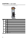
CHAPTER 2 PART NAMES
2
1)
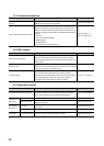
ERR. LED
Indicates the error status of the master/local module. The description of the errors can be confirmed in CC-
Link IE Field Network diagnostics. ( Page 124, CHAPTER 9)
ON
One of the following errors has occurred:
• A stop error occurs in the safety CPU module.
• An error was detected in all stations.
• Modules with same station number exist on the network.
• A network parameter is corrupted.
• The network parameter does not match the installation status. (Reserved station specification, number of
connected stations, network number etc.)
Flashing A data link faulty station was detected.
OFF Working normally.
L ERR. LED
Indicates the error status of the received data and the circuit. When the L ERR. LED is on, you can check
the L ER LED for "P1" or "P2" to see on which port the error was detected.
The description of the errors can be confirmed in CC-Link IE Field Network diagnostics. ( Page 124,
CHAPTER 9)
This LED automatically turns off when the module has received normal data and loopback is completed in
ring topology.
ON
• The module has received abnormal data.
• The module is performing loopback.
OFF
• The module has received normal data.
• The module is not performing loopback.
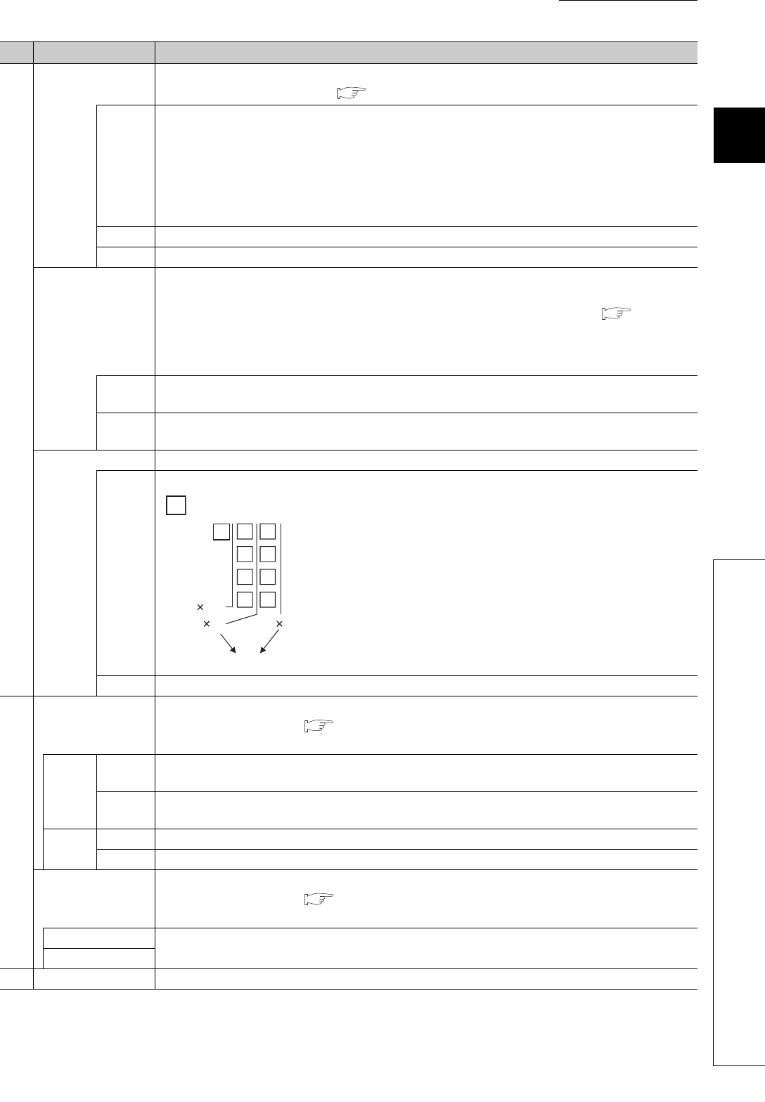
ST.NO. Displays the station number of the master/local module.
ON
Displays the station number.
Station No. 15
OFF Operates as a master station (safety station). (station No. 0)
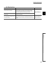
2)
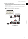
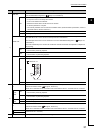
P1
PORT1 connector for CC-Link IE Field Network (RJ45 connector)
Connect an Ethernet cable. ( Page 64, Section 6.3)
There are no restrictions on the connection order of the cables for the "P1" connector and "P2" connector.
L ER
LED
ON
• The module has received abnormal data.
• The module is performing loopback.
OFF
• The module has received normal data.
• The module is not performing loopback.
LINK
LED
ON Linkup in progress.
OFF Linkdown in progress.
P2
PORT2 connector for CC-Link IE Field Network (RJ45 connector)
Connect an Ethernet cable. ( Page 64, Section 6.3)
There are no restrictions on the connection order of the cables for the "P1" connector and "P2" connector.
L ER LED
(Same as the "P1" connector)
LINK LED
3)
Serial number display Displays the serial number printed on the rating plate.
No. Name Application
Ex.
10 5+=15
1
4
1
100
1
10