


2
4
I
7
8
325
INDEX
0 to 9
32-bit data assurance . . . . . . . . . . . . . . . . . . . . . 106
A
Applicable CPU modules and number of modules . . 58
Applicable systems . . . . . . . . . . . . . . . . . . . . . . . . 58
Assurance of cyclic data integrity . . . . . . . . . . . . . 106
Asynchronous. . . . . . . . . . . . . . . . . . . . . . . . . . . . 83
Automatic return . . . . . . . . . . . . . . . . . . . . . . . . . . 36
B
Bend radius . . . . . . . . . . . . . . . . . . . . . . . . . . . . . 66
Block data assurance per station . . . . . . . . . . 83,108
C
Cable test. . . . . . . . . . . . . . . . . . . . . . . . . . . . . . . 74
Cables . . . . . . . . . . . . . . . . . . . . . . . . . . . . . . . . . 56
Canceling/Restoring reserved station setting . . . . .142
Cascade connection . . . . . . . . . . . . . . . . . . . . . . . 50
CC-Link IE Field Network. . . . . . . . . . . . . . . . . 15,19
CC-Link IE Field Network configuration . . . . . . . . . . 47
CC-Link IE Field Network diagnostics . . . . . . . . . . 124
CC-Link Safety master module . . . . . . . . . . . . . . . . 15
Checking for failure of any other than the master/local
module
. . . . . . . . . . . . . . . . . . . . . . . . . . . . . . . 237
Checking for failure of the master/local module . . .238
Checking on the rating plate. . . . . . . . . . . . . . . . . 321
Checking the LEDs . . . . . . . . . . . . . . . . . . . . . . .239
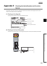
Checking the serial number and function version . . 321
Communication Example of when Safety Stations and a
Standard Station are Used
. . . . . . . . . . . . . . . . . . 211
Communication is unstable . . . . . . . . . . . . . . . . . 245
Communication Target Station No. . . . . . . . . . . . . . 91
Communication test . . . . . . . . . . . . . . . . . . . . . . . 75
Communication with different networks . . . . . . . . . 118
Comparison between the CC-Link Safety master module
and the master/local module . . . . . . . . . . . . . . . . 313
Comparison between the Q series master/local module
and the master/local module
. . . . . . . . . . . . . . . .317
Compliance with the EMC, low voltage, and machinery
directives
. . . . . . . . . . . . . . . . . . . . . . . . . . . . . . . . 6
CONFIG. . . . . . . . . . . . . . . . . . . . . . . . . . . . . . . 263
Connecting the cable. . . . . . . . . . . . . . . . . . . . . . . 64
Constant scan . . . . . . . . . . . . . . . . . . . . . . . . . . . 83
Cyclic transmission . . . . . . . . . . . . . . . . . . . . . . .102
Cyclic transmission cannot be performed. . . . . . . . 243
Cyclic transmission delay time . . . . . . . . . . . . . . . 304
D
D LINK LED . . . . . . . . . . . . . . . . . . . . . . . . . . . . . 30
Data flow . . . . . . . . . . . . . . . . . . . . . . . . . . . . . . 103
DATA LINK . . . . . . . . . . . . . . . . . . . . . . . . . . . . 263
Data link faulty station setting. . . . . . . . . . . . . . . . . 85
Diagnostic Items . . . . . . . . . . . . . . . . . . . . . . . . . 124
Diagnostic Window . . . . . . . . . . . . . . . . . . . . . . . 130
Disconnecting the cable . . . . . . . . . . . . . . . . . . . . 65
E
ERR. LED . . . . . . . . . . . . . . . . . . . . . . . . . . . . . . 31
Error code list. . . . . . . . . . . . . . . . . . . . . . . . . . . 246
Error invalid station. . . . . . . . . . . . . . . . . . . . . . . 120
Error invalid station setting. . . . . . . . . . . . . . . . . . 120
Error log registration function . . . . . . . . . . . . . . . . . 99
Ethernet adapter module . . . . . . . . . . . . . . . . . . . . 15
Ethernet cable connection . . . . . . . . . . . . . . . . . . . 64
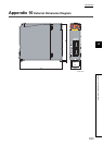
External dimensions . . . . . . . . . . . . . . . . . . . . . . . 34
F
Function list . . . . . . . . . . . . . . . . . . . . . . . . . . . . . 35
G
General specifications. . . . . . . . . . . . . . . . . . . . . . 33
GX Developer . . . . . . . . . . . . . . . . . . . . . . . . . . . 58
GX Works2 . . . . . . . . . . . . . . . . . . . . . . . . . . 15,58
H
Handling . . . . . . . . . . . . . . . . . . . . . . . . . . . . . . . 66
Hardware test. . . . . . . . . . . . . . . . . . . . . . . . . . . . 60
Head module . . . . . . . . . . . . . . . . . . . . . . . . . . . . 15
Hubs . . . . . . . . . . . . . . . . . . . . . . . . . . . . . . . . . . 57
I
Input and output status settings in case of failure . . 113
Installation . . . . . . . . . . . . . . . . . . . . . . . . . . . . . . 59
Installation and wiring . . . . . . . . . . . . . . . . . . . . . . 59
Intelligent device station . . . . . . . . . . . . . . . . . . . . 16
Interlock program . . . . . . . . . . . . . . . . . . . . . . . . 109
Internal current consumption (5VDC) . . . . . . . . . . . 34
J
JP/GP.READ . . . . . . . . . . . . . . . . . . . . . . . . . . . 160
JP/GP.REQ (reading/writing clock data) . . . . . . . . 194
JP/GP.SWRITE . . . . . . . . . . . . . . . . . . . . . . . . . 187
JP/GP.WRITE . . . . . . . . . . . . . . . . . . . . . . . . . . 175
L
L ER LED . . . . . . . . . . . . . . . . . . . . . . . . . . . . . . 31
L ERR. LED . . . . . . . . . . . . . . . . . . . . . . . . . . . . . 31
L series master/local module . . . . . . . . . . . . . . . . . 15
Link dedicated instruction . . . . . . . . . . . . . . . . . . 152
Link device. . . . . . . . . . . . . . . . . . . . . . . . . . . . . . 16
Link device area . . . . . . . . . . . . . . . . . . . . . . . . . . 42
Link device area (buffer memory address: 0 to 18975
(0
H
to 4A1F
H
)) . . . . . . . . . . . . . . . . . . . . . . . . . . 266
Link device assignment . . . . . . . . . . . . . . . . . . . . 103