


42
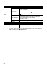
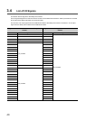
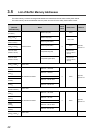
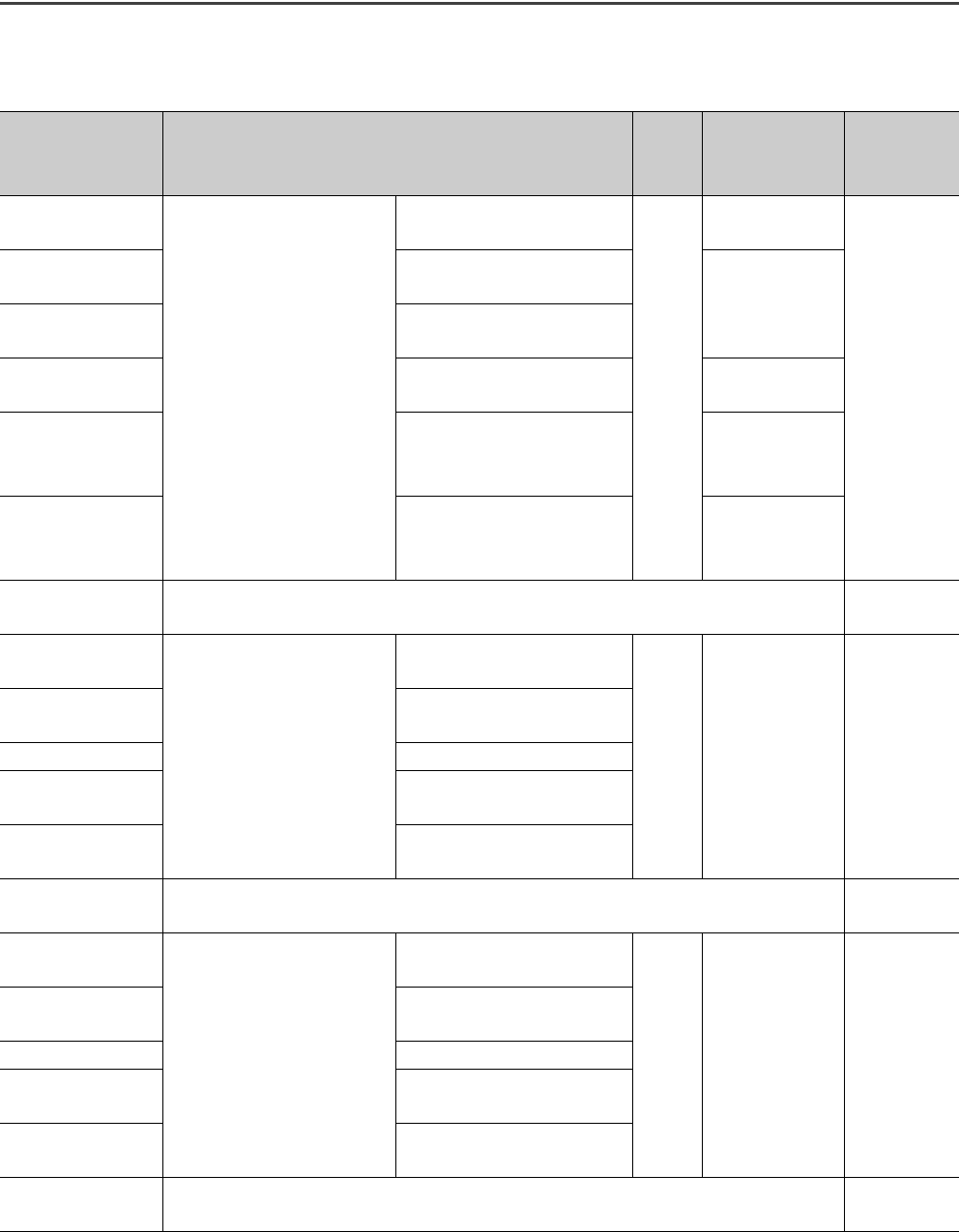
3.5 List of Buffer Memory Addresses
The buffer memory is used to exchange data between the master/local module and the safety CPU module.
The buffer memory values are defaulted when the power is turned off or the safety CPU module is reset.
Address
(Decimal
(Hexadecimal))
Name
Initial
value
Read, write Refer to
0 to 1023
(0 to 3FF
H
)
Link device area
Remote input (RX)
0
Read
Page 266,
Appendix 2.1
1024 to 2047
(400
H
to 7FF
H
)
Remote output (RY)
Read, write
2048 to 10239
(800
H
to 27FF
H
)
Remote register (RWw)
10240 to 18431
(2800
H
to 47FF
H
)
Remote register (RWr) Read
18432 to 18463
(4800
H
to 481F
H
)
Link special relay (SB)
• 18432 to 18433 for
read and write
• 18434 to 18463 for
read only
18464 to 18975
(4820
H
to 4A1F
H
)
Link special register (SW)
• 18464 to 18495 for
read and write
• 18496 to 18975 for
read only
18976 to 19455
(4A20
H
to 4BFF
H
)
System area
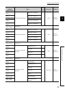
19456
(4C00
H
)
RX offset/size information
Station No. 1 RX offset
0 Read
Page 269,
Appendix 2.2
19457
(4C01
H
)
Station No. 1 RX size
to to
19694
(4CEE
H
)
Station No. 120 RX offset
19695
(4CEF
H
)
Station No. 120 RX size
19696 to 19711
(4CF0
H
to 4CFF
H
)
System area
19712
(4D00
H
)
RY offset/size information
Station No. 1 RY offset
0 Read
Page 269,
Appendix 2.3
19713
(4D01
H
)
Station No. 1 RY size
to to
19950
(4DEE
H
)
Station No. 120 RY offset
19951
(4DEF
H
)
Station No. 120 RY size
19952 to 19967
(4DF0
H
to 4DFF
H
)
System area