


Operating Instructions Teledyne API - Model T200H/T200M Operation Manual
110
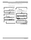
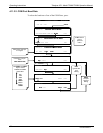
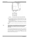
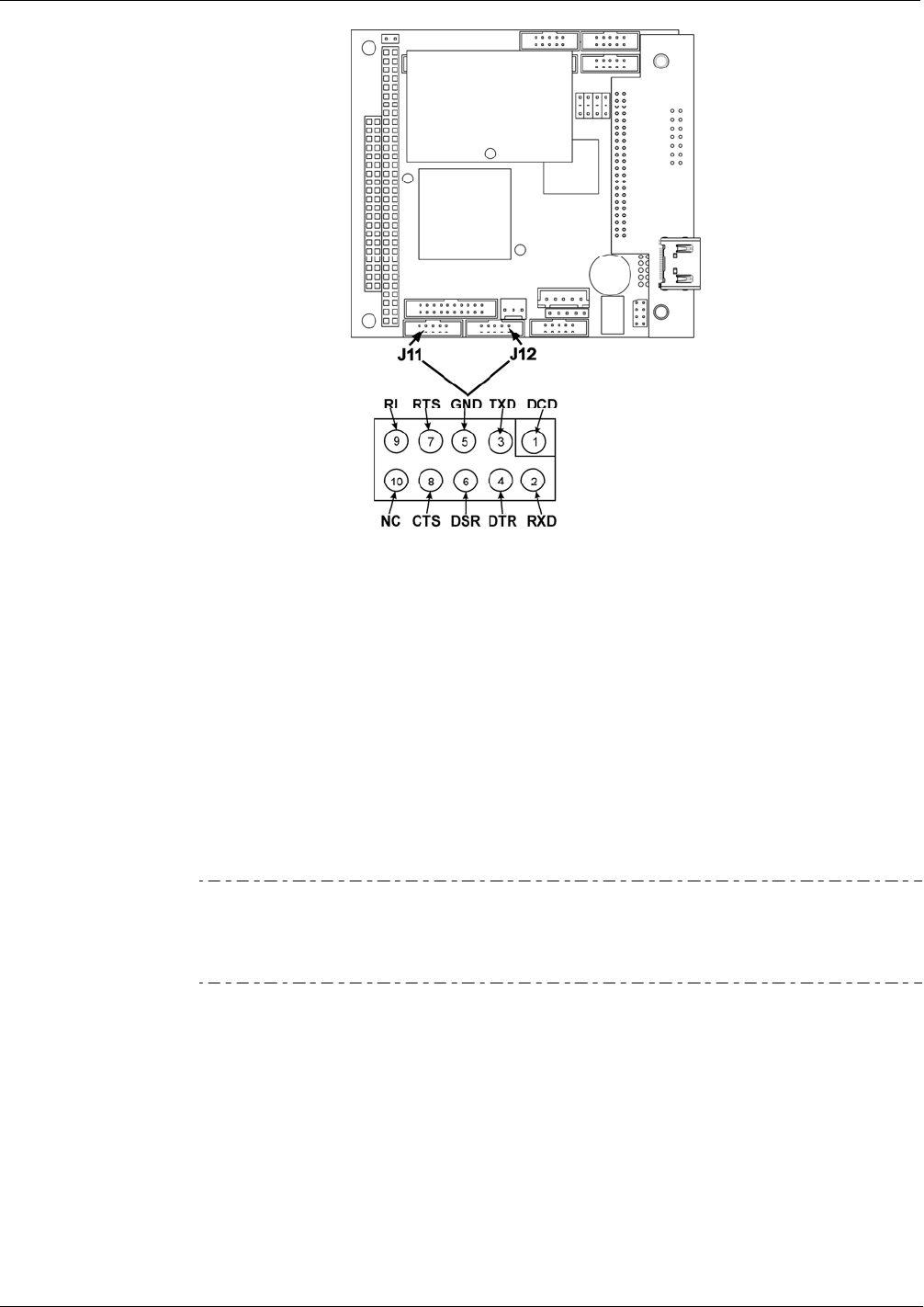
Figure 4-6: CPU COM1 & COM2 Connector Pin-Outs for RS-232 Mode
Teledyne API offers two mating cables, one of which should be applicable for your use.
Part number WR000077, a DB-9 female to DB-9 female cable, 6 feet long. Allows
connection of COM1 with the serial port of most personal computers. Also available
as Option 60 (see Section 5.9.1).
Part number WR000024, a DB-9 female to DB-25 male cable. Allows connection to
the most common styles of modems (e.g. Hayes-compatible) and code activated
switches.
Both cables are configured with straight-through wiring and should require no additional
adapters.
Note Cables that appear to be compatible because of matching connectors may
incorporate internal wiring that make the link inoperable. Check cables
acquired from sources other than Teledyne API for pin assignments
before using.
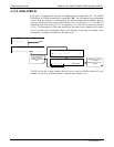
To assist in properly connecting the serial ports to either a computer or a modem, there
are activity indicators LEDs labeled RX and TX) just above the rear panel RS-232 port.
Once a cable is connected between the analyzer and a computer or modem, both the red
and green LEDs should be on. If the RX TX LEDs for RS232 are not lit, change
position of rear panel DCE DTE mode switch (see 4.11.1). If both LEDs are still not
illum
inated, check the cable for proper wiring.
07270B DCN6512