Teledyne API - Model T200H/T200M Operation Manual Troubleshooting & Repair
253
7.5.16.2. Sample Pressure
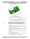
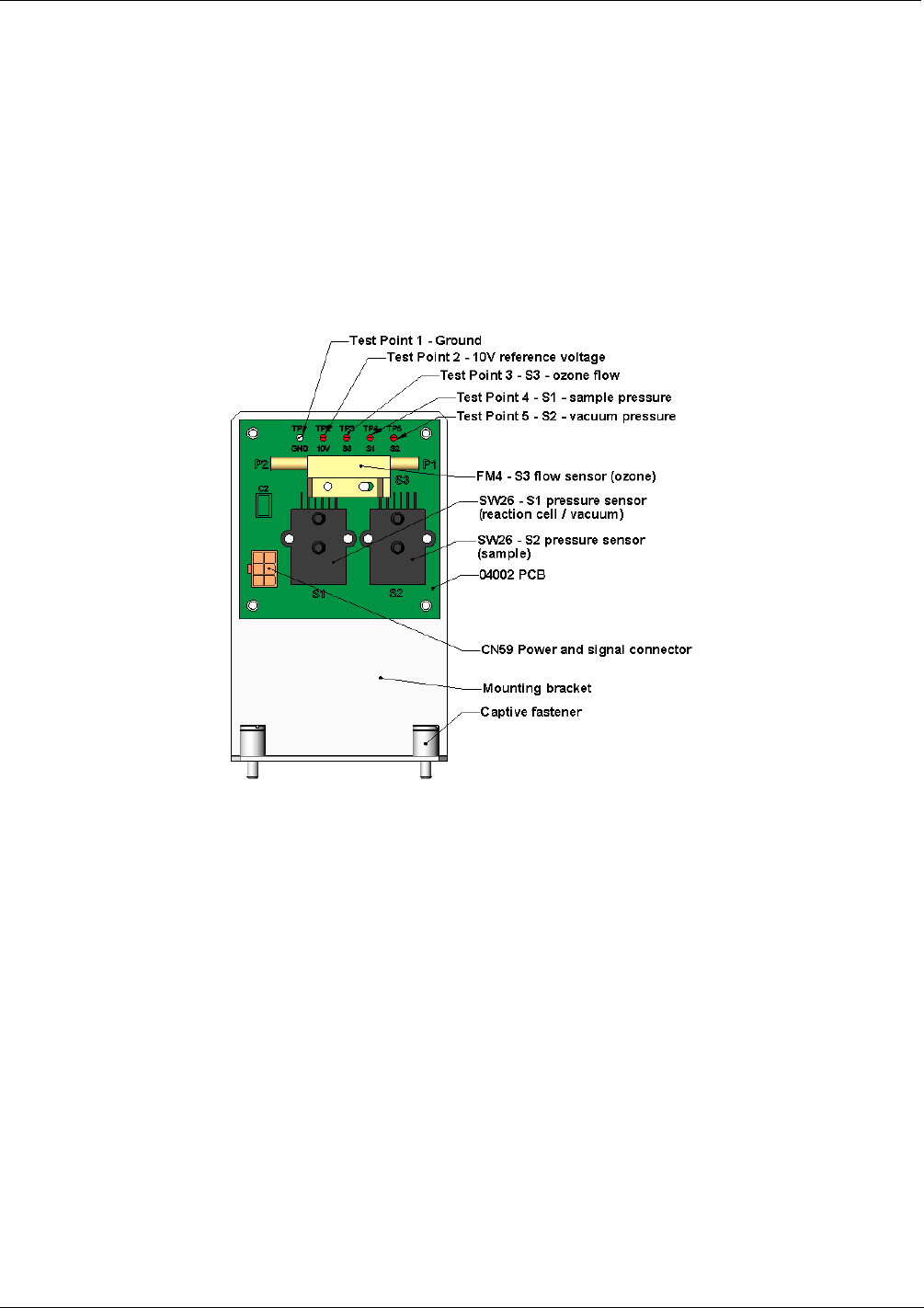
Measure the voltage across test points TP1 and TP4. With the sample pump
disconnected or turned off, this voltage should be 4500 250 mV. With the pump
running, it should be about 0.2 V less as the sample pressure drops by about 1 in-Hg-A
below ambient pressure. If this voltage is significantly different, the pressure transducer
S2 or the board may be faulty. A leak in the sample system to vacuum may also cause
this voltage to be between about 0.6 and 4.5. Make sure that the front panel reading of
the sample pressure is at about 1 in-Hg-A less than ambient pressure. Ensure that the
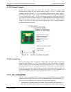
tubing is connected to the upper port, which is closer to the sensor’s contacts; the lower
port does not measure pressure.
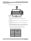
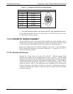
Figure 7-16: Pressure / Flow Sensor Assembly
7.5.16.3. Ozone Flow
Measure the voltage across TP1 and TP3. With proper ozone flow (250 cm
3
/min), this
should be approximately 3.0 ± 0.3 V (this voltage will vary with altitude). With flow
stopped (pump turned off), the voltage should be approximately 0 V. If the voltage is
incorrect, the flow sensor or the board may be faulty. A cross-leak to vacuum inside the
Perma Pure dryer may also cause this flow to increase significantly, and the voltage will
increase accordingly. Also, make sure that the gas flows from P1 to P2 as labeled on the
flow sensor (“high” pressure P1 to “low” pressure P2 or “Port” 1 to “Port” 2).
7.5.17. NO
2
CONVERTER
The NO
2
converter assembly can fail in two ways, an electrical failure of the band heater
and/or the thermocouple control circuit and a performance failure of the converter itself.
NO
2
converter heater failures can be divided into two possible problems:
Temperature is reported properly but heater does not heat to full temperature. In
this case, the heater is either disconnected or broken or the power relay is broken.
07270B DCN6512


