


Principles of Operation Teledyne API - Model T200H/T200M Operation Manual
276
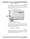
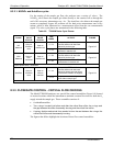
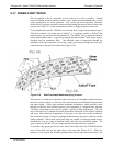
8.3.2.1. NO/NO
x
and AutoZero cycles
For the routing of the sample gas flow, the analyzer uses a variety of valves. The
NO/NO
X
valve directs the sample gas either directly to the reaction cell or through the
unit’s NO
2
converter, alternating every ~4 s. The AutoZero valve directs the sample gas
stream to completely bypass the reaction cell for dark noise measurement once every
minute, which is then subtracted as a measurement offset from the raw concentration
signal. The valve cycle phases are summarized in the following table.
Table 8-2: T200H/M Valve Cycle Phases
PHASE
NO/ NO
X
VALVE
STATUS
AUTOZERO
VALVE
STATUS
TIME
INDEX
ACTIVITY FIGURE
0 - 2 s
Wait period (NO dwell time).
Ensures reaction cell has been
flushed of previous gas.
NO
Measure
Open to
AutoZero
valve
Open to
reaction cell
2 - 4 s
Analyzer measures chemilumi-
nescence in reaction cell.
Figure 8-2
4 – 6 s
Wait period (NOX dwell time).
Ensures reaction cell has been
flushed of previous gas.
NOX
Measure
Open to
NO
2
converter
Open to
reaction cell
6 – 8 s
Analyzer measures NO + O3 chemi-
luminescence in reaction cell.
Figure 8-2
Cycle repeats every ~8 seconds
0 – 4 s
Wait period (AZERO dwell time).
Ensures reaction cell has been
flushed of sample gas and chemi-
luminescence reaction is stopped.
AutoZero
Open to
AutoZero
valve
Open to
vacuum
manifold
4 - 6 s
Analyzer measures background
noise without sample gas
Figure 8-4
Cycle repeats every minute
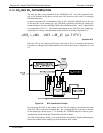
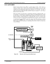
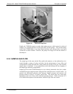
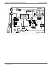
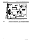
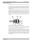
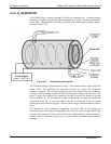
8.3.3. FLOW RATE CONTROL - CRITICAL FLOW ORIFICES
The Model T200H/M analyzers use special flow control assemblies (Figure 8-8) located
at various locations within the instrument to maintain constant flow rates for both the O
3
supply air and the sample gas. These assemblies consists of:
A critical flow orifice.
Two o-rings: Located just before and after the critical flow orifice, the o-rings seal
the gap between the walls of assembly housing and the critical flow orifice.
A spring: Applies mechanical force needed to form the seal between the o-rings, the
critical flow orifice and the assembly housing.
The figures that follow highlight the location of these flow control assemblies:
07270B DCN6512