


Getting Started Teledyne API - Model T200H/T200M Operation Manual
34
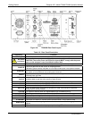
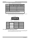
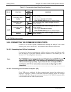
Table 3-1: Analog Output Data Type Default Settings
CHANNEL DEFAULT SETTING
PARAMETER
A1 A2 A3 A4
3
DATA TYPE
1
NXCNC1 NOCNC1 N2CNC1 NXCNC2
RANGE 0 - 5 VDC
2
REC OFS 0 mVDC
AUTO CAL. ON
CALIBRATED NO
OUTPUT ON
SCALE 100 ppm
UPDATE 5 sec
1
See Table A-6 of T200H/M Appendix A for definitions of these DAS data types
2
Optional current loop outputs are available for analog output channels A1-A3.
3
On analyzers with O
2
sensor options installed, DAS parameter O2CONC is assigned to output A4.
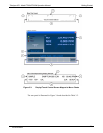
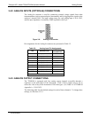
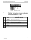
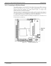
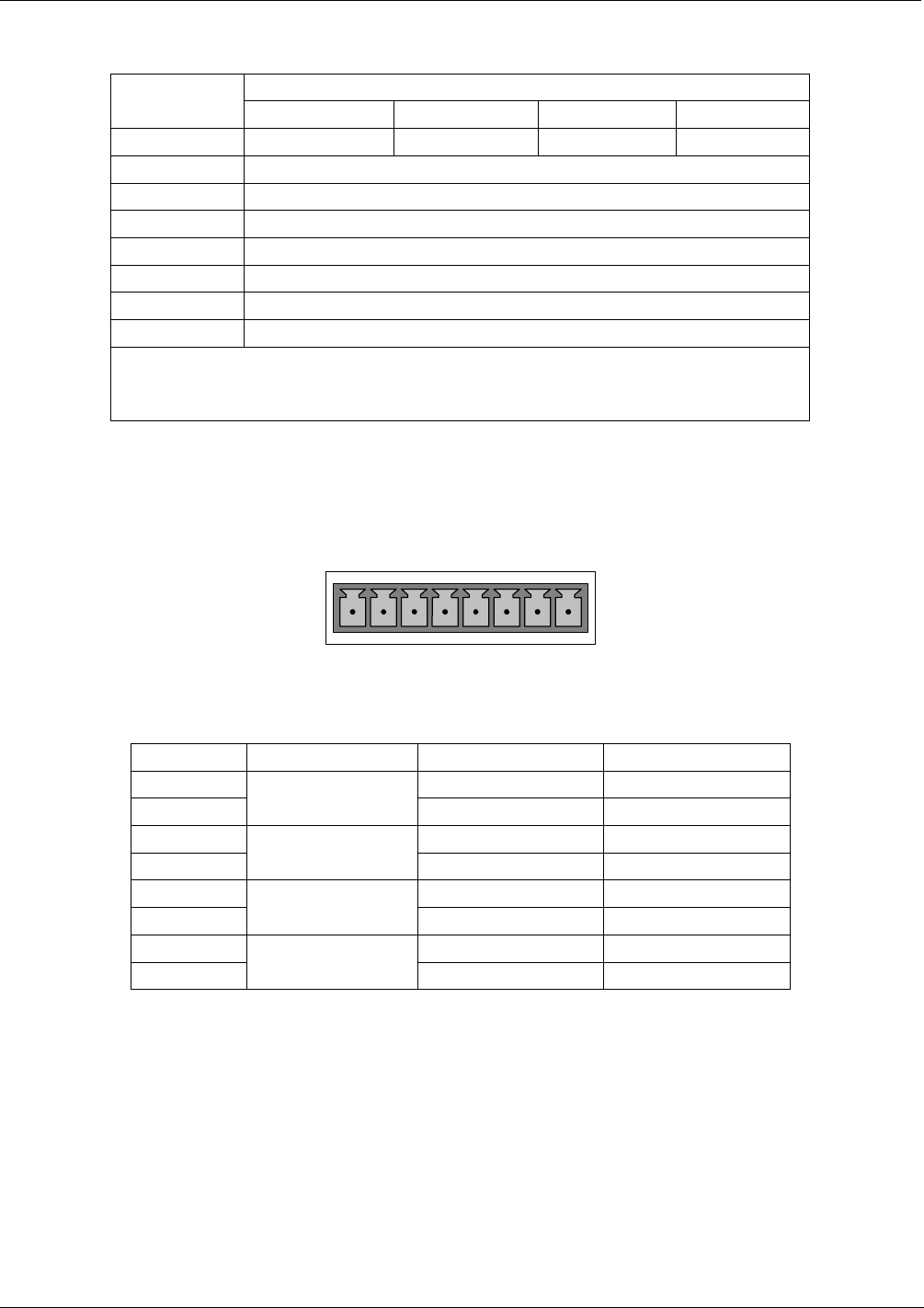
To access these signals attach a strip chart recorder and/or data-logger to the appropriate
contacts of the analog output connecter on the rear panel of the analyzer.
A
NALOG OUT
A1
A
2
A
3
A
4
+ - + - + - + -
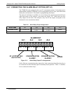
Figure 3-7: Analog Output Connector
Table 3-4: Analog Output Pin-Outs
PIN ANALOG OUTPUT VOLTAGE SIGNAL CURRENT SIGNAL
1 V Out I Out +
2
A1
Ground I Out -
3 V Out I Out +
4
A2
Ground I Out -
5 V Out I Out +
6
A3
Ground I Out -
7 V Out Not Available
8
A4
Ground Not Available
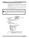
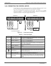
3.4.4. CONNECTING THE STATUS OUTPUTS
The analyzer’s status outputs to interface with a device that accepts logic-level digital
inputs, such as programmable logic controller (PLC) chips, are accessed through a 12
pin connector labeled STATUS on the analyzer’s rear panel.
07270B DCN6512