


Troubleshooting & Repair Teledyne API - Model T200H/T200M Operation Manual
252
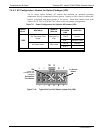
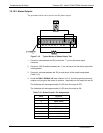
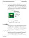
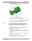
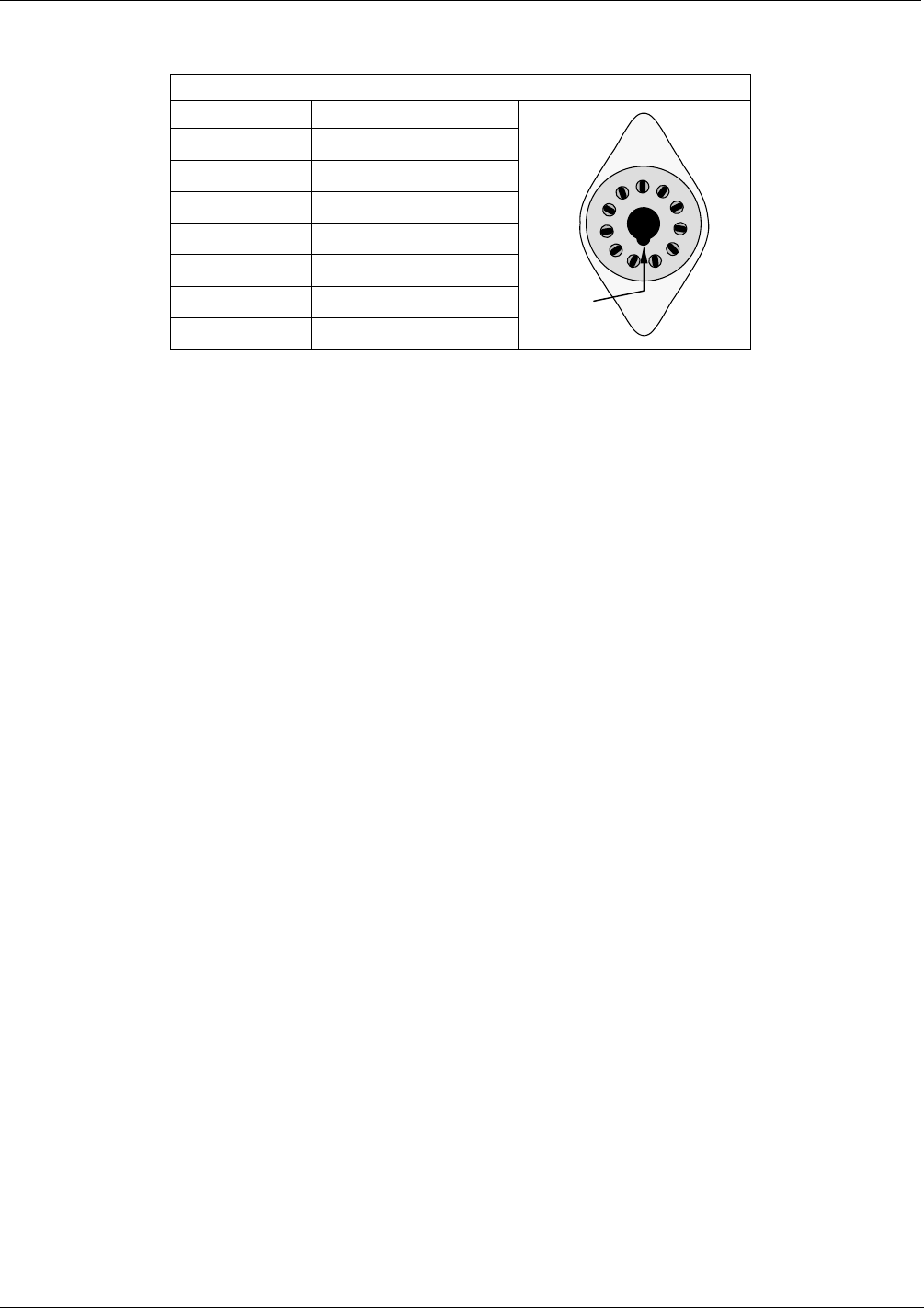
Table 7-11: Example of HVPS Power Supply Outputs
If HVPS reading = 700 VDC
PIN PAIR NOMINAL READING
1 2 70 VDC
2 3 70 VDC
3 4 70 VDC
4 5 70 VDC
5 6 70 VDC
6 7 70 VDC
7 8 70 VDC
KEY
5
6
7
8
9
10
11
1
2
3
4
Turn off the instrument power, and reconnect the PMT, then reassemble the sensor.
If any faults are found in the test, you must obtain a new HVPS as there are no user
serviceable parts inside the supply.
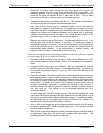
7.5.16. PNEUMATIC SENSOR ASSEMBLY
The pressure/flow sensor circuit board, located behind the sensor assembly, can be
checked with a voltmeter using the following procedure, which assumes that the wiring
is intact and that the motherboard and the power supplies are operating properly.
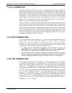
Measure the voltage across TP1 and TP2, it should be 10.0 0.25 V. If not, the board is
faulty. Measure the voltage across the leads of capacitor C2. It should be 5.0 ± 0.25 V,
if not, the board may be faulty.
7.5.16.1. Reaction Cell Pressure
Measure the voltage across test points TP1 and TP5. With the sample pump
disconnected or turned off, the voltage should be 4500 250 mV. With the pump
running, it should be 800-1700 mV depending on the performance of the vacuum pump.
The lower the reaction cell pressure, the lower the resulting voltage is. If this voltage is
significantly different, the pressure transducer S1 or the board may be faulty. If this
voltage is between 2 and 5 V, the pump may not be performing well, check that the
reaction cell pressure is less than 10 in-Hg-A (at sea level). Ensure that the tubing is
connected to the upper port, which is closer to the sensor’s contacts; the lower port does
not measure pressure.
07270B DCN6512