


Teledyne API - Model T200H/T200M Operation Manual Operating Instructions
153
4.13.6.3. Manual Calibration of Analog Outputs Configured for Current Loop Ranges
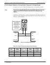
The current loop output option (see Section 5.4) uses a small converter assembly to
change the DC voltage output by the standard voltage output to a current signal ranging
between 0-20 mA. Since the exact current increment per voltage count varies from
converter to converter and from instrument to instrument, analog outputs with this
option installed cannot be calibrated automatically and must be adjusted manually.
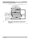
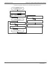
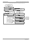
Adjusting the signal zero and full scale values of the current loop output is done in a
similar manner as manually adjusting analog outputs configured for voltage output
except that:
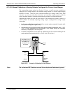
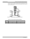
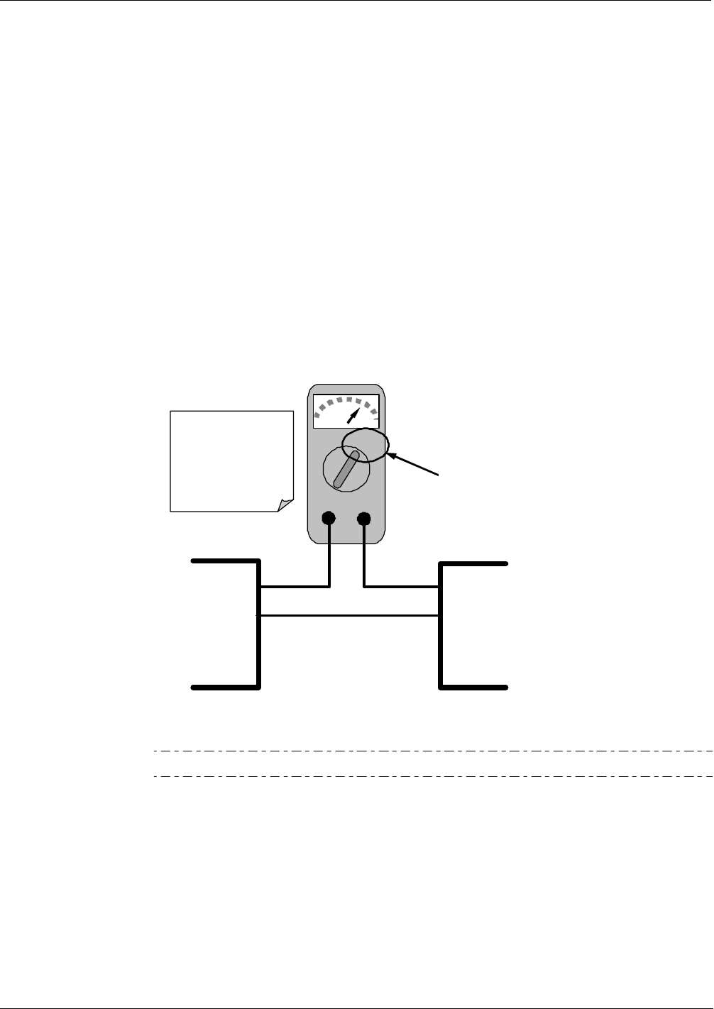
In this case calibration is performed with a current meter connected in series with
the output circuitry (See Figure 4-12).
Adjustments to the output are made using the front panel touchscreen, also in 100,
10 or 1 count increments, but the change in the voltage driving the converter
assembly is displayed on the front panel.
As before, adjustment of the output is performed until the current reading of the
meter reaches the desired point (e.g. 2 mA, 4 mA, 20 mA, etc.)
mA
IN OUT
I OUT +
I OUT -
I IN +
I IN -
Recording
Device
Analyzer
See Table 3-2 for
pin assignments of
the Analog Out
connector on the
rear panel.
Current
Meter
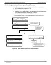
Figure 4-12: Setup for Calibrating Current Outputs
Note
Do not exceed 60 V between current loop outputs and instrument ground.
07270B DCN6512