Teledyne API - Model T200H/T200M Operation Manual Troubleshooting & Repair
241
7.5.4. AC POWER CONFIGURATION
The T-Series digital electronic systems will operate with any of the specified power
regimes. As long as instrument is connected to 100-120 VAC or 220-240 VAC at either
50 or 60 Hz it will turn on and after about 30 seconds show a front panel display.
Internally, the status LEDs located on the Relay PCA, Motherboard and CPU should
turn on as soon as the power is supplied.
On the other hand, some of the analyzer’s non-digital components, such as the pump and
the various AC powered heaters must be properly configured for the type of power being
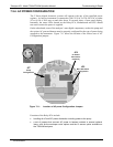
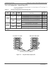
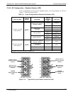
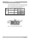
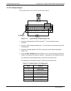
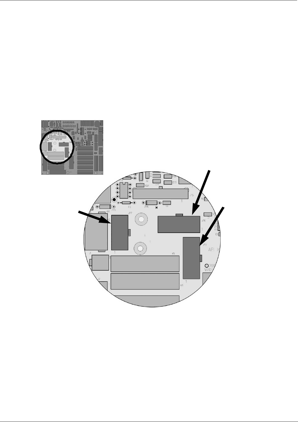
supplied to the instrument. Figure 7-11 shows the location of the various sets of AC
Configuratio
n jumpers.
JP2
Main AC Heater
Configuration
JP6
O
2
Sensor
Connection.
(optional)
JP7
Pump
Configuration
Figure 7-11: Location of AC power Configuration Jumpers
Functions of the Relay PCA include:
handling all AC and DC power distribution including power to the pump.
a set of jumpers that connect AC power to heaters included in several optional
items, such as the zero/span valve options and the O
2
sensor option available on
the T200H/M analyzers.
07270B DCN6512


