


Teledyne API - Model T200H/T200M Operation Manual Getting Started
51
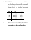
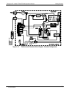
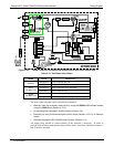
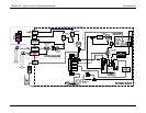
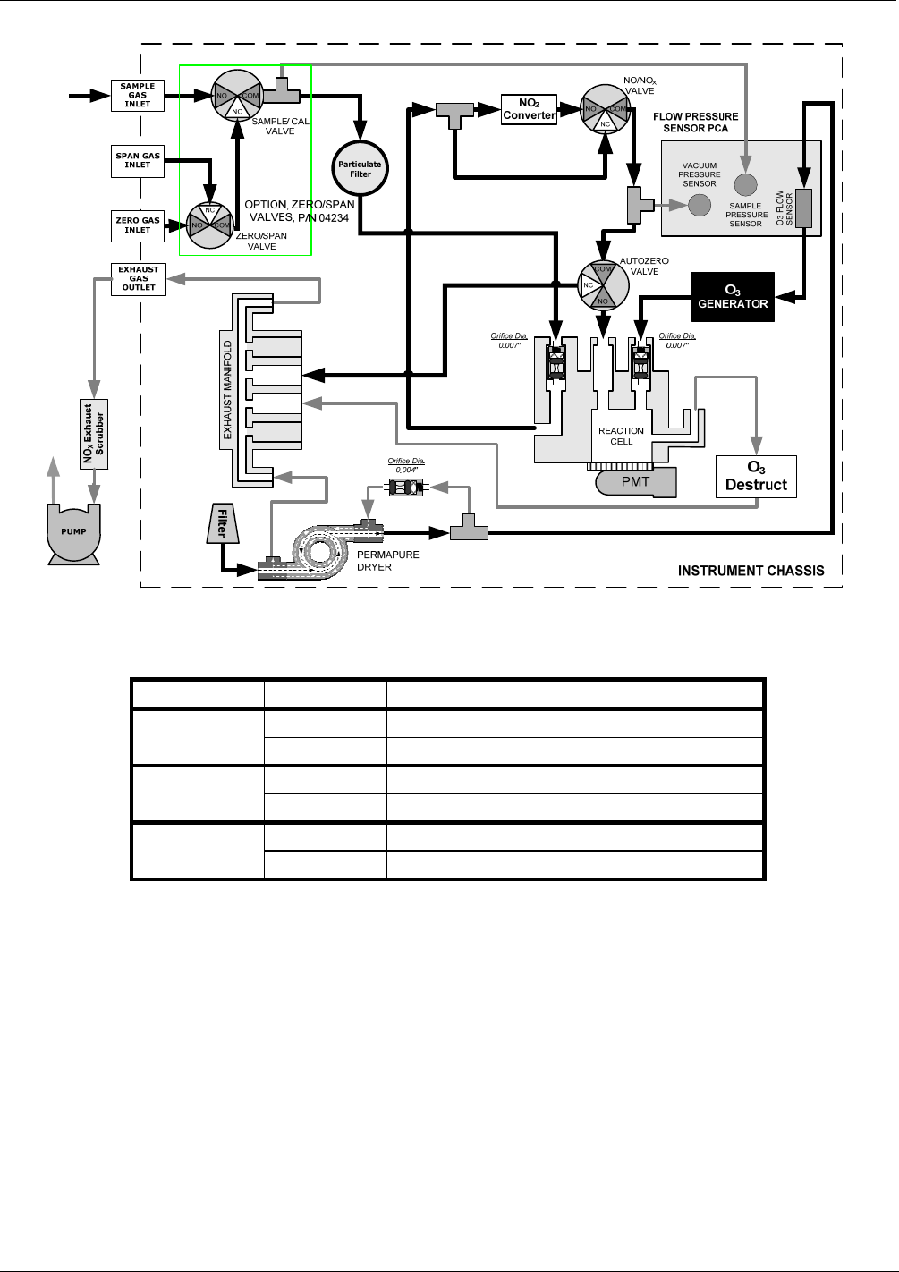
Figure 3-20: T200M – Internal Pneumatics with Ambient Zero-Span Valve Option 50A
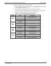
Table 3-10: Zero/Span Valve States
MODE VALVE CONDITION
Sample/Cal Open to sample gas inlet
SAMPLE
Zero/Span Open to zero air inlet
Sample/Cal Open to zero/span inlet (activated)
ZERO
CALIBRATION
Zero/Span Open to zero air inlet
Sample/Cal Open to zero/span inlet (activated)
SPAN
CALIBRATION
Zero/Span Open to span gas inlet / IZS gas (activated)
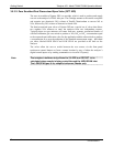
The state of the zero/span valves can also be controlled:
Manually from the analyzer’s front panel by using the SIGNAL I/O controls located
under the DIAG Menu (Section 4.13.2),
By activating the instrument’s AutoCal feature (Section 5.8),
Remotely by using the external digital control inputs (Section 4.15.1.2) or Ethernet
option.
Remotely through the RS-232/485 serial I/O ports (Section 4.11).
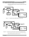
All supply lines should be vented outside of the analyzer’s enclosure. In order to
prevent back-diffusion and pressure drop effects, these vent lines should be between 2
and 10 meters in length.
07270B DCN6512