


Principles of Operation Teledyne API - Model T200H/T200M Operation Manual
296
be adjusted through a potentiometer. These adjustments should only be performed when
encountering problems with the software calibration that cannot be rectified otherwise.
See Section 11.6.3.8 for this hardware calibration.
To
Motherboard
PMT Preamp PCA
Low
Pass Noise
Filter
E Test Control
From CPU
MUX
Amp to
Voltage
Converter/
Amplifier
D-A
Converter
PMT
Coarse
Gain Set
(Rotary
PMT Fine
Gain Set
(Rotary
Switch)
PMT
Signal
Offset
E-Test
Generator
O-Test
Generator
O Test Control
From CPU
PMT Temp
Sensor
PMT
Temperature
Feedback
Circuit
TEC Control
PCA
PMT Output
PMT HVPS
Drive Voltage
PMT Temp Analog Signal
to Motherboard
PMT Output Signal
(PMT) to Motherboard
O Test
LED
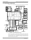
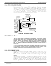
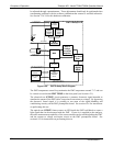
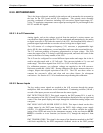
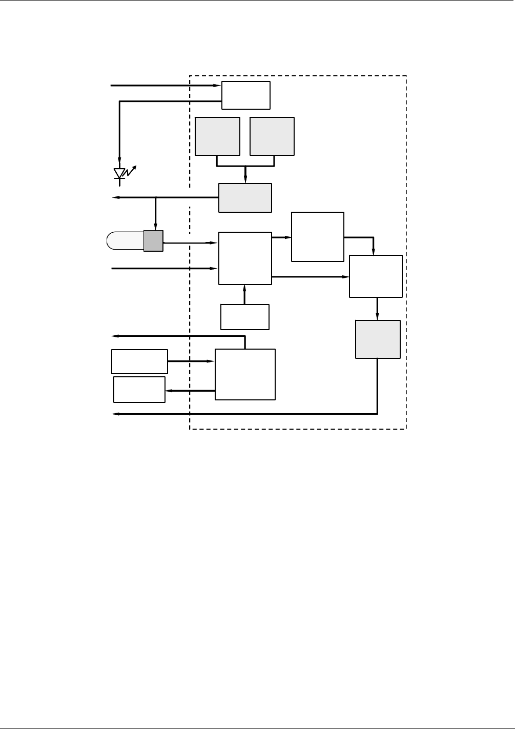
Figure 8-20: PMT Preamp Block Diagram
The PMT temperature control loop maintains the PMT temperature around 7° C and can
be viewed as test function PMT TEMP on the front panel (see Section 6.2.1).
The electrical test (ETEST) circuit generates a constant, electronic signal intended to
simulate the output of the PMT (after conversion from current to voltage). By bypassing
the detector’s actual signal, it is possible to test most of the signal handling and
conditioning circuitry on the PMT preamplifier board. See section 6.9.6 for instructions
on performing this test.
The optical test (OTEST) feature causes an LED inside the PMT cold block to create a
light signal that can be measured with the PMT. If zero air is supplied to the analyzer,
the entire measurement capability of the sensor module can be tested including the PMT
and the current to voltage conversion circuit on the PMT preamplifier board. See
section 6.9.5 for instructions on performing this test.
07270B DCN6512