


217
7. TROUBLESHOOTING & REPAIR
This section contains a variety of methods for identifying and solving performance
problems with the analyzer.
CAUTION
The operations outlined in this Section must be performed by qualified
maintenance personnel only.
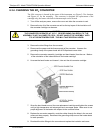
WARNING
Risk of electrical shock. Some operations need to be carried out with
the analyzer open and running. Exercise caution to avoid electrical
shocks and electrostatic or mechanical damage to the analyzer. Do not
drop tools into the analyzer or leave those after your procedures. Do
not shorten or touch electric connections with metallic tools while
operating inside the analyzer. Use common sense when operating
inside a running analyzer.
7.1. GENERAL TROUBLESHOOTING
The analyzer has been designed so that problems can be rapidly detected, evaluated and
repaired. During operation, the analyzer continuously performs diagnostic tests and
provides the ability to evaluate its key operating parameters without disturbing
monitoring operations.
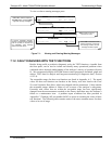
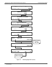
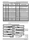
A systematic approach to troubleshooting will generally consist of the following five
steps:
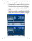
any warning messages and take corrective action as necessary.
Examine the values of all TEST functions and compare them to factory values. any
major deviations from the factory values and take corrective action.
Use the internal electronic status LED’s to determine whether the electronic
communication channels are operating properly. Verify that the DC power supplies
are operating properly by checking the voltage test points on the relay board. that
the analyzer’s DC power wiring is color-coded and these colors match the color of
the corresponding test points on the relay board.
Suspect a leak first! Technical Support data indicate that the majority of all problems
are eventually traced to leaks in the pneumatic system of the analyzer (including the
external pump), the source of zero air or span gases or the sample gas delivery
system. Check for gas flow problems such as clogged or blocked internal/external
gas lines, damaged seals, punctured gas lines, a damaged pump diaphragm, etc.
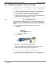
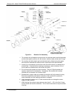
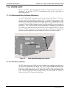
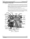
Follow the procedures defined in Section 3.6.3. to confirm that the analyzer’s vital
function
s are working (power supplies, CPU, relay board, PMT cooler, etc.). See
Figure 3-5 for general layout of components a
nd sub-assemblies in the analyzer.
See the wiring interconnect diagram and interconnect list in Appendix D.
07270B DCN6512