


Teledyne API - Model T200H/T200M Operation Manual Troubleshooting & Repair
225
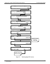
7.2. GAS FLOW PROBLEMS
The T200H/M has two main flow paths, the sample flow and the flow of the ozone
supply air. With zero/span valve option installed, there is a third (zero air) and a fourth
(span gas) flow path, but either one of those is only controlled by critical flow orifices
and not displayed on the front panel or stored to the DAS. The full flow diagrams of the
standard configuration and with options installed (Appendix D, document 04574) help in
trouble-shooting flow problems. In general, flow problems can be divided into three
categories:
Flow is too high
Flow is greater than zero, but is too low, and/or unstable
Flow is zero (no flow)
When troubleshooting flow problems, it is essential to confirm the actual flow rate
without relying on the analyzer’s flow display. The use of an independent, external flow
meter to perform a flow check as described in Section 4.13.7.5 is essential.
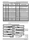
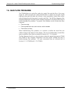
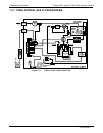
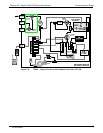
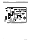
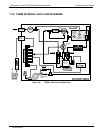
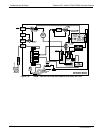
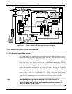
The flow diagram
s found in a variety locations within this manual depicting the T200H
and T200M in their standard configuration and with options installed can help in
trouble-shooting flow problems. For your convenience they are collected here in
Sections 11.2.1 (T200H) and 11.2.2 (T200M)
07270B DCN6512