


Operating Instructions Teledyne API - Model T200H/T200M Operation Manual
122
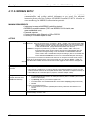
4.11.10. MODBUS SETUP
The following set of instructions assumes that the user is familiar with MODBUS
communications, and provides minimal information to get started. For additional
instruction, please refer to the Teledyne API MODBUS manual, PN 06276. Also refer to
www.modbus.org for MODBUS communication protocols.
MINIMUM REQUIREMENTS
Instrument firmware with MODBUS capabilities installed.
MODBUS-compatible software (TAPI uses MODBUS Poll for testing; see
www.modbustools.com)
Personal computer
Communications cable (Ethernet or USB or RS232)
Possibly a null modem adapter or cable
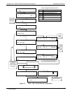
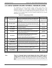
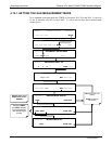
ACTIONS
Set Com Mode parameters
Comm
Slave ID
Ethernet: Using the front panel menu, go to SETUP – MORE – COMM – INET; scroll through the INET
submenu until you reach TCP PORT 2 (the standard setting is 502), then continue to TCP
PORT 2 MODBUS TCP/IP; press EDIT and toggle the menu button to change the setting
to ON, then press ENTR. (Change Machine ID if needed: see “Slave ID”).
USB/RS232: Using the front panel menu, go to SETUP – MORE – COMM – COM2 – EDIT; scroll
through the COM2 EDIT submenu until the display shows COM2 MODBUS RTU: OFF
(press OFF to change the setting to ON. Scroll NEXT to COM2 MODBUS ASCII and
ensure it is set to OFF. Press ENTR to keep the new settings. (If RTU is not available with
your communications equipment, set the COM2 MODBUS ASCII setting to ON and
ensure that COM2 MODBUS RTU is set to OFF. Press ENTR to keep the new settings).
If your analyzer is connected to a network with at least one other analyzer of the same model, a unique
Slave ID must be assigned to each. Using the front panel menu, go to SETUP – MORE – COMM – ID.
The MACHINE ID default is the same as the model number. Toggle the menu buttons to change the ID.
Reboot analyzer For the settings to take effect, power down the analyzer, wait 5 seconds, and power up the analyzer.
Make appropriate cable
connections
Connect your analyzer either:
via its Ethernet or USB port to a PC (this may require a USB-to-RS232 adapter for your PC; if so, also
install the software driver from the CD supplied with the adapter, and reboot the computer if required), or
via its COM2 port to a null modem (this may require a null modem adapter or cable).
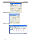
Specify MODBUS software
settings
(examples used here are for
MODBUS Poll software)
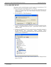
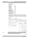
1. Click Setup / [Read / Write Definition] /.
a. In the Read/Write Definition window (see example that follows) select a Function (what you wish
to read from the analyzer).
b. Input Quantity (based on your firmware’s register map).
c. In the View section of the Read/Write Definition window select a Display (typically Float Inverse).
d. Click OK.
2. Next, click Connection/Connect.
a. In the Connection Setup window (see example that follows), select the options based on your
computer.
b. Press OK.
Read the Modbus Poll Register Use the Register Map to find the test parameter names for the values displayed (see example that follows
If desired, assign an alias for each.
07270B DCN6512