


Principles of Operation Teledyne API - Model T200H/T200M Operation Manual
300
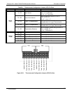
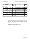
Table 8-5: Typical Thermocouple Settings
TC
TYPE
TERMINATION
TYPE
OUTPUT
SCALE TYPE
JUMPER
BETWEEN
PINS
USED ON
JUMPER
COLOR
INPUT TC1 (J15)
K
GROUNDED 5mV / °C
2 – 12
4 – 14
T200H/M with Mini HiCon Converter
BROWN
K
ISOLATED 5mV / °C
2 – 12
4 – 14
5 – 15
T200H/M with Mini HiCon Converter
GREY
K
ISOLATED 10mV / °C
4 – 14
5 – 15
T200H/M models with Moly Converter
PURPLE
J
ISOLATED 10mV / °C
1 – 11
3 – 13
5 – 15
T200H/M models with Moly Converter
RED
J
GROUNDED 10mV / °C
1 – 11
3 – 13
T200H/M models with Moly Converter
GREEN
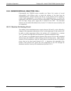
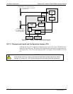
8.5.7.4. Valve Control
The relay board also hosts two valve driver chips, each of which can drive up four
valves. The main valve assembly in the T200H/M is the NO/NO
X
- Auto-zero solenoid
valve assembly mounted right in front of the NO
2
converter housing. These two valves
are actuated with 12 V supplied from the relay board and driven by the CPU through the
I
2
C bus.
A second set of valves may be installed if the zero/span valve is enabled in the analyzer.
Specialty manifold valves may be present in the analyzer.
07270B DCN6512