


Teledyne API - Model T200H/T200M Operation Manual Getting Started
49
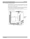
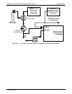
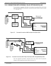
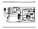
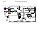
3.5.3. CONNECTIONS WITH INTERNAL VALVE OPTIONS INSTALLED
If your analyzer is equipped with either the zero/span valve option (50A) or the 2-span
point valve option (50D), the pneumatic connections should be made as shown in Figure
3-17 and
Figure 3-18:
VENT here if input
is pressurized
Source of
SAMPLE Gas
PUMP
Instrument
Chassis
Sample
Exhaust
Span Point
Zero Air
Calibrated NO
at HIGH Span
Concentration
MODEL T700
Gas Dilution
Calibrator
MODEL 701
Zero Gas
Generator
Figure 3-17: Pneumatic Connections–With Zero/Span Valve Option (50A)
VENT here if input
is pressurized
Source of
SAMPLE Gas
PUMP
VENT
Instrument
Chassis
Sample
Exhaust
High Span Point
Low Span Point
Zero Air
Calibrated NO
at HIGH Span
Concentration
Calibrated NO
at LOW Span
Concentration
VENT
On/Off
Valves
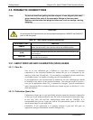
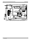
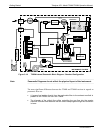
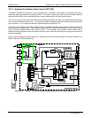
Figure 3-18: Pneumatic Connections–With 2-Span Point Option (50D) –Using Bottled Span Gas
Once the appropriate pneumatic connections have been made, check all pneumatic
fittings for leaks using the procedures defined in Section 7.5.
07270B DCN6512