


Teledyne API - Model T200H/T200M Operation Manual Principles of Operation
289
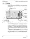
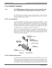
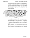
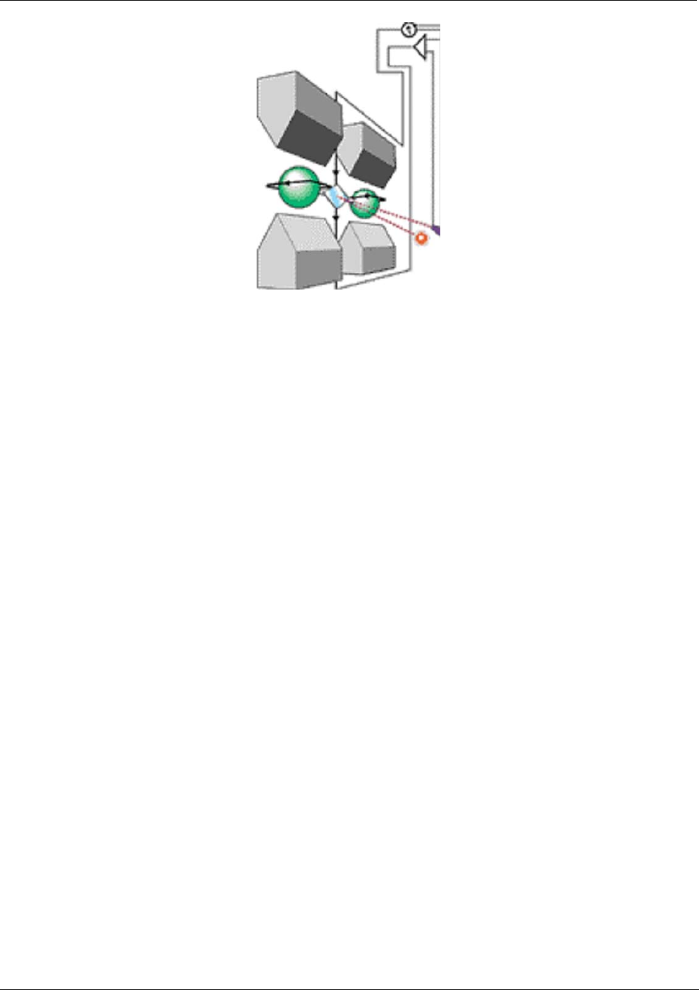
Figure 8-14: Oxygen Sensor - Principle of Operation
8.4.2. OPERATION WITHIN THE T200H/M ANALYZER
The oxygen sensor option is transparently integrated into the core analyzer operation.
All functions can be viewed or accessed through the front panel, just like the functions
for NO
X
.
The O2 concentration is displayed in the upper right-hand corner, alternating with
NOX, NO and NO2 concentrations.
Test functions for O2 slope and offset are viewable from the front panel along with
the analyzer’s other test functions.
O2 sensor calibration is performed via the front panel CAL function and is
performed in a nearly identical manner as the standard NOX/NO calibration. See
Section 5 for more details.
Stability of the O
2
sensor can be viewed (see 3.3.2.1)
The O
2
concentration range is 0-100% (user selectable) with 0.1% precision and
accuracy and is available to be output via one of the instrument’s four user selectable
analog outputs (see Section 6.13.4).
The temperature of the O
2
sensor is maintained at a constant 50° C by means of a PID
loop and can be viewed on the front panel as test function O2 TEMP.
The O
2
sensor assembly itself does not have any serviceable parts and is enclosed in an
insulated canister.
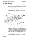
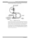
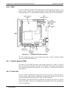
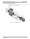
8.4.3. PNEUMATIC OPERATION OF THE O
2
SENSOR
Pneumatically, the O
2
sensor is connected after the particulate filter and draws a flow of
about 80 cm³/min in addition to the normal sample flow rate (See Table 10.-3 for
nominal sample inlet gas flow rates) and is separately controlled with its own critical
flow orifice located inside the vacuum manifold.
07270B DCN6512